BMR Suspension TAS005 User Manual
Page 6
(CONTINUED)
holes in the cross-member will “self-align” the drill bit, forcing the bit to center itself.
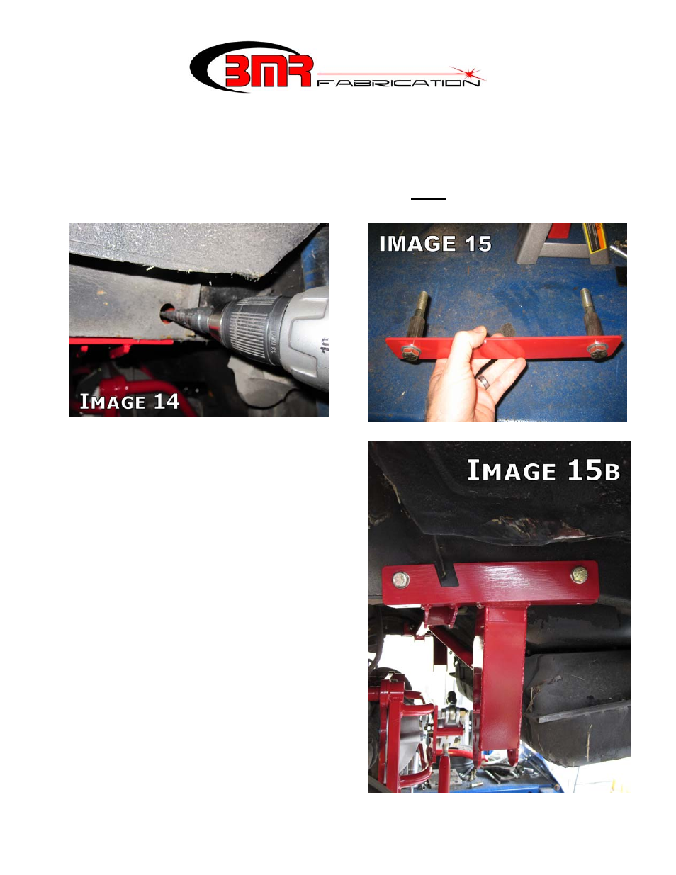
28. Once both ½” holes are drilled through the sub frame, it is necessary to enlarge the outer
frame holes to ¾” to allow insertion of the provided frame reinforcement inserts. Using
either a ¾” drill bit or a step bit (much easier), enlarge ONLY the outer holes in the frame
rail. (Image 14)
6
29. Assemble the outer reinforcement plate,
frame inserts, ½” bolts and stainless washers
as shown in Image 15. There are 2 different
length frame spacers. The ½” x 3.25” bolt
and 1.85” spacer goes in the rear hole while
the ½” x 3.5” bolt and 2.2” spacer goes in
the front hole. Slide the assembly through
the subframe until the bolts protrude through
the BMR cross-member on the inside of the
frame rail. Thread a nut and stainless
washer onto the exposed portion of the bolts
and then tighten these bolts to 80 ft/lbs.
30. Proceed to the driver’s side. The driver’s
side frame rail has a frame reinforcement
that makes it differ from the passenger side.
This requires a different reinforcement plate.
Position the plate as shown in Image 15b
and duplicate steps 24-29 using the
remaining spacers and same length bolts.