BMR Suspension TAS005 User Manual
Page 8
8
(CONTINUED)
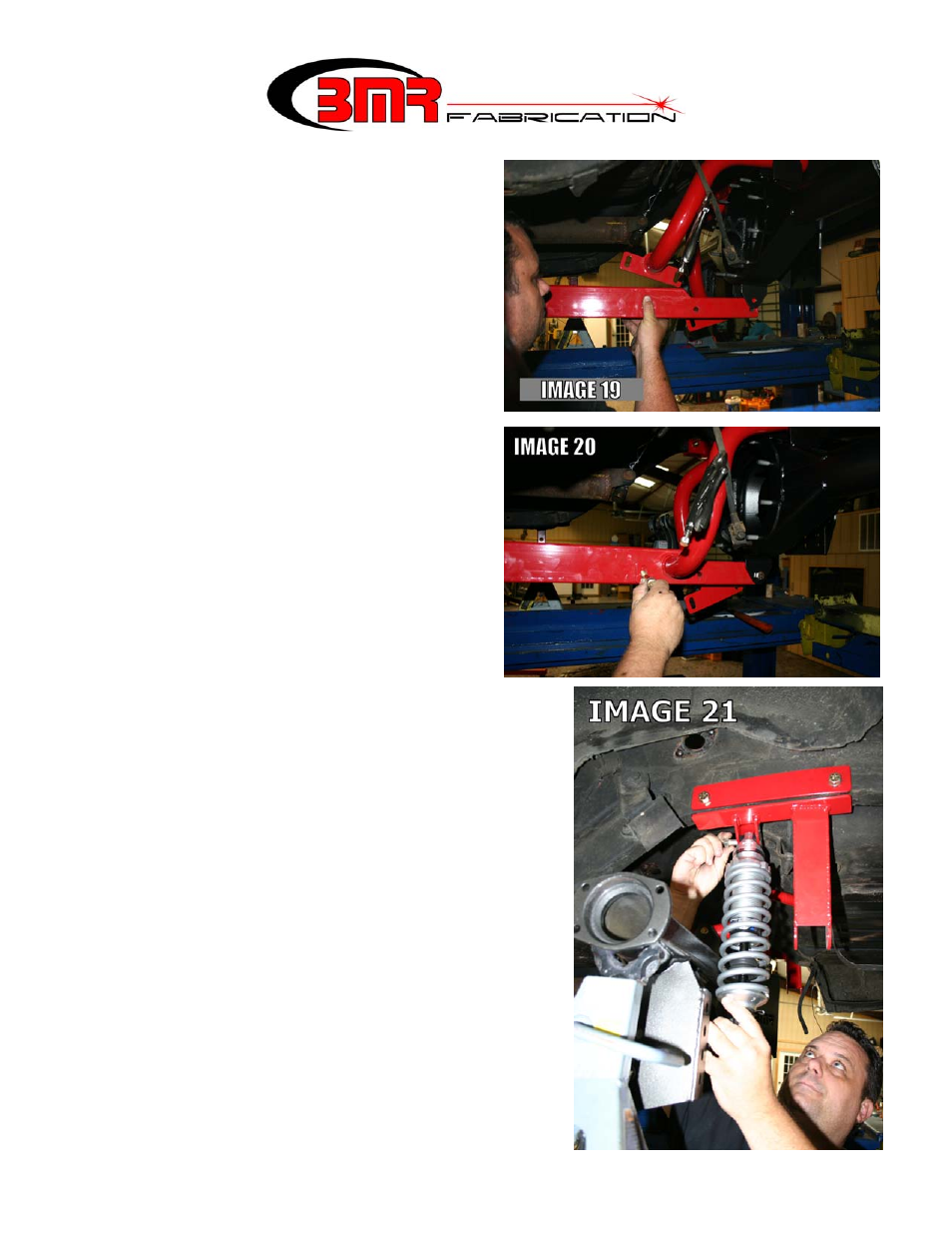
38. Lift the rear of the torque arm and connect
it to the lower mount of the BMR 9” axle
housing using one of the provided ½” x
3.25” bolts, nuts, & stainless washer.
Leave bolts finger tight. (Image 19)
39. Position the upper torque arm mounts onto
the torque arm and line up the mounting
holes as in Image 13 above. Insert the two
provided ½” x 3.25” bolts, nuts, and (4)
large diameter washers, positioning one
washer on each side. The two mounting
plates should “sandwich” the torque arm
between them. Leave all bolts finger tight.
(Image 20)
40. Slide the upper mount of the shock into the BMR
cross-member making sure the shock adjustment
knobs are facing inward. Insert the supplied ½” x
2.5” bolt. Repeat for the other side. Thread a
stainless washer and nut onto the bolt and tighten to
80 ft/lbs. Repeat for the other side. (Image 21)
41. Assemble the bottom shock mount as shown in
Image 16b above using the provided 5/8” x 4” bolt.
Place a 5/8” small diameter washer on either side of
the poly bushings. Insert the bolt into one of the
middle shock mounts located on the control arm
mount. NOTE: it may be necessary to raise or
lower the rear end in order to insert the bolt.
(Image 17)
42. Place a large diameter washer over the 5/8” bolt
inside the control arm mount and then thread a nut
onto the bolt. Tighten to 80 ft/lbs.
43. Repeat steps 40-44 for the other side.