9 port mapping – HP Integrity Superdome 2 Server User Manual
Page 163
9 Port mapping
Device bay port mapping for Superdome 2 Compute Enclosures
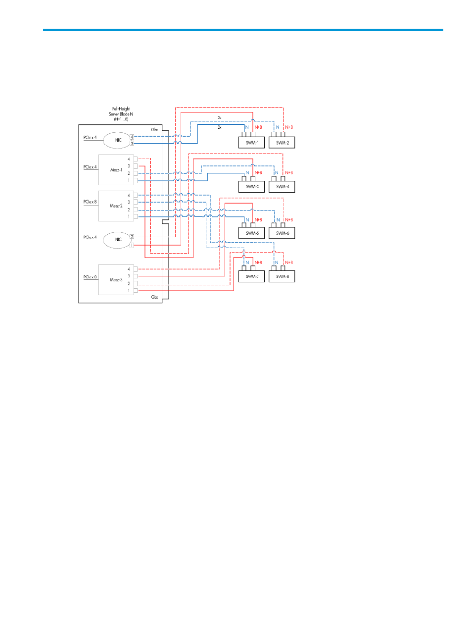
Superdome 2 Server Blade
In this diagram, N equals the number of the blade in the enclosure and the port number for the
switch. For example, if a blade is inserted into slot 1, it is considered device 1. Because full-height
server blades take up the space of two half-height server blades, the enclosure is limited to a
maximum of eight full-height server blades. Port mapping from these full-height server blades can
initially appear to be different from the half-height server blades, but they use similar conventions.
Just as in a half-height server blade, if a blade is inserted into slot 1, it is considered device 1, but
it has a second set of ports that also map to switches 1 and 2. With the full-height server blade,
an N/N+8 scheme is used on the switches. Therefore, server blade 1 maps to ports 1 and 9 on
both switches, as N=1. For a server blade inserted into slot 2, the 4 ports used on switches 1 and
2 are 2 and 10, as N=2.
Device bay port mapping tabular view for Superdome 2 compute enclosures
If a device is not present, the check box is disabled and the port cannot be viewed.
The server blades are mapped to the interconnect bays in the following manner:
Superdome 2 server blade
•
Embedded NICs 1 and 3 (ENET:1 and ENET:3) map to interconnect bay 1.
•
Embedded NICs 2 and 4 (ENET:2 and ENET:4) map to interconnect bay 2.
Device bay port mapping for Superdome 2 Compute Enclosures 163