Refer to table 3 for, Refer to table 4 – Alliance Laundry Systems PHM802N User Manual
Page 32
© Copyright, Alliance Laundry Systems LLC – DO NOT COPY or TRANSMIT
Specifications and Dimensions
F8138601
30
IMPORTANT: Do not block the overflow vent
above the drain line.
If water or suds flow from the overflow vent and the
machine has been verified to be operating properly
with proper water levels and correct amount of laundry
chemicals, a drain line may be added to the vent and
routed to a drain trough.
1. Remove the riveted bracket on the rear panel for
access to the overflow vent pipe.
2. Route a drain pipe from the vent pipe to a drain
trough. Drain pipe should be routed straight
across or down and be suspended above drain
trough by at least 3 inches (7.62 cm).
IMPORTANT: Do not route the overflow vent pipe
to a direct drain system.
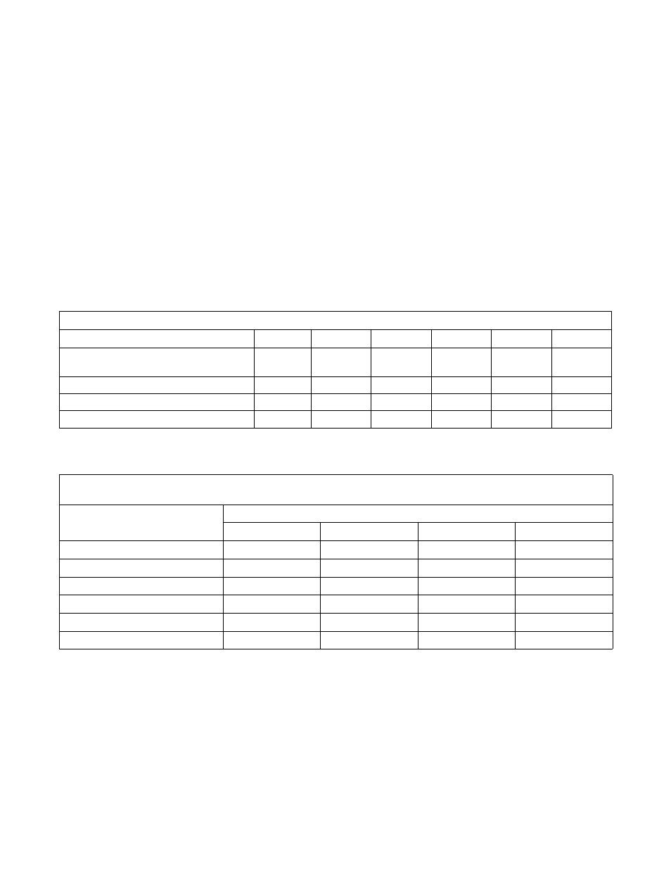
Drain Information
Specifications
35
60
80
100
125
150
Drain connection size, O.D., in. (mm)
with second drain:
2.375 (60)
3 (76)
3 (76)
3 (76)
3 (76)
3 (77)
Number of drain outlets
1
1
2
2
2
2
Drain flow capacity, gal/min. (l/min.)
35 (132)
64 (242)
120 (454)
120 (454)
140 (530)
140 (530)
Recommended drain pit size, ft
3
(l)
†
5 (142)
6 (170)
9 (255)
11 (311)
13 (368)
13 (368)
†Sized for one machine using overflow level.
Table 3
Drain Line Sizing
Minimum Drain I.D., in. (mm)
Model
Number of Machines
1
2
3
4
35
3 (76.2)
3 (76.2)
3.5 (88.9)
4 (102)
60
3 (76.2)
4 (102)
6 (152)
6 (152)
80
4 (102)
6 (152)
6 (152)
8 (203)
100
4 (102)
6 (152)
6 (152)
8 (203)
125
4 (102)
6 (152)
6 (152)
8 (203)
150
4 (102)
6 (152)
6 (152)
8 (203)
Table 4