E-m-hc2 probes-v1_26 – ROTRONIC HC2 User Manual
Page 27
E-M-HC2 Probes-V1_26
Rotronic AG
Bassersdorf, Switzerland
Document code
Unit
HygroClip 2 (HC2) Humidity Temperature
Probes: User Guide
Instruction Manual
Document Type
Page 27 of 31
Document title
© 2009-2013; Rotronic AG E-M-HC2 Probes-V1_26
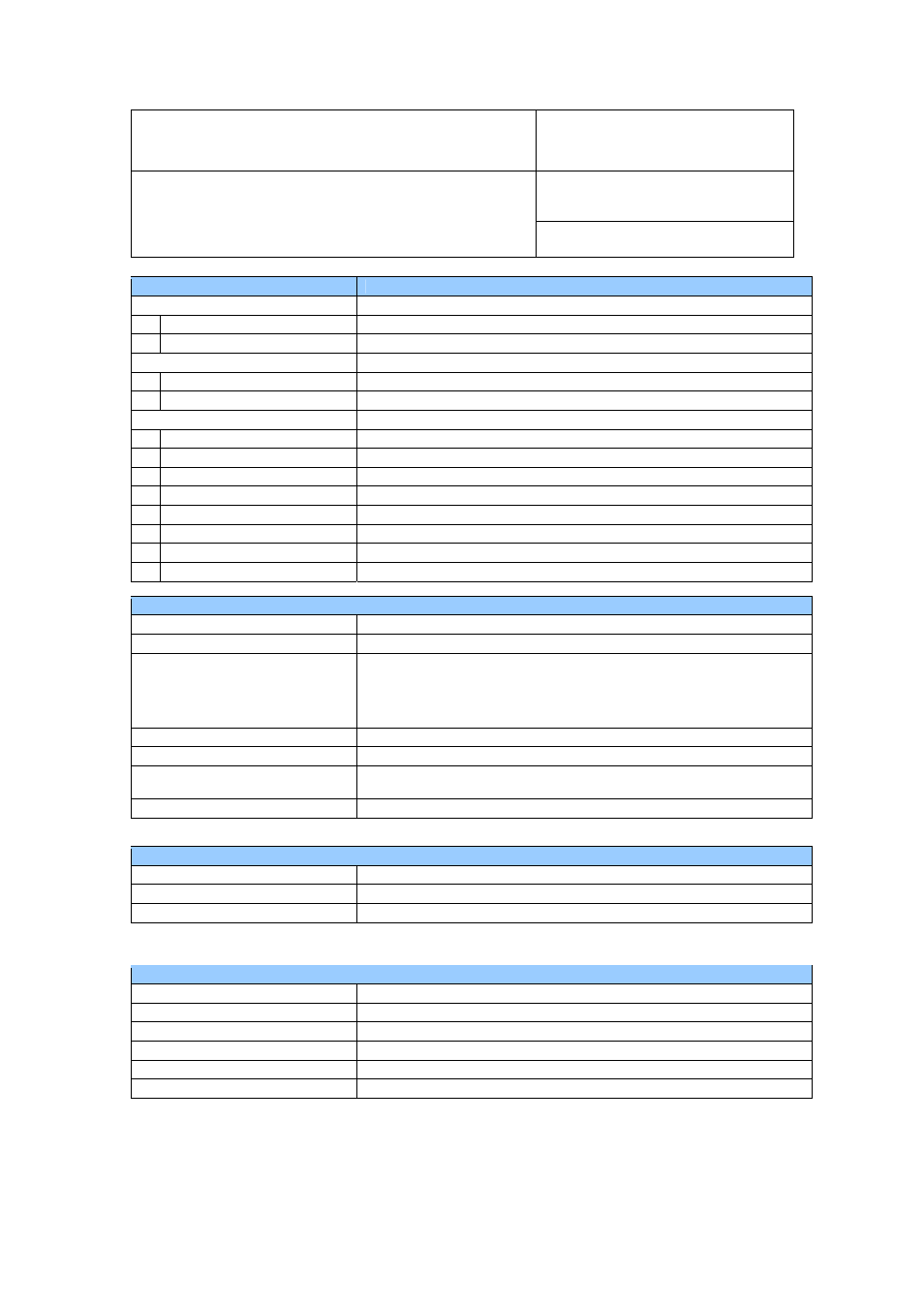
Configurable analog outputs
Output 1
Can be made to correspond to any parameter
Factory default parameter
Relative humidity
Factory default scale
0…100 %RH
Output 2
Can be made to correspond to any parameter
Factory default parameter
Temperature
Factory default scale
-40…60 °C
Output 1 and Output 2
Signal
type
0…1
V
User configurable scaling limits
-999.99 … 9999.99 engineering units
Offset at 0 V
+ 3 mV (maximum)
Ripple
< 1.2 mV/x 2µs
Short circuit tolerant
Yes
Internal resistance
< 10 Ω
Minimum external load
1000 Ω
Deviation from digital signal
< ±1 mV from 0.002 to 1.0 V / + 2 mV from 0.0 to 0.002 V
Digital interface
Interface type
UART (Universal Asynchronous Receiver Transmitter)
Organization
Dialog, duplex
Default configuration
Baud rate : 19200
Parity : none
Data bits : 8
Stop bits : 1
Flow Control : none
Tolerance 3
%
Baud rate configuration:
No
Logical levels
Logical 0: < = 0.3V * VDD
Logical 1: > = 0.8V * VDD
Maximum cable length
5 m (16.4 ft) w/o signal booster
Effect of VDD in the range 3.3 to 5.0 V (see note below)
Temperature (digital)
<0.05 °C
Humidity (digital)
<0.25 %RH
Analog signals
<2mV (reference: digital value)
Note: for models HC2-IC, HC2-IM and HC2-IE, VDD is limited to 3.3 V ± 0.1V
General specifications
Housing material
See Models
Collar material (connector)
Alu-Anticorodal (anodized)
Dust filter material
See Models
Protection grade
IP 65
Physical dimensions
See Models
Weight See
Models