E-m-hc2 probes-v1_26, 8maintenance – ROTRONIC HC2 User Manual
Page 24
E-M-HC2 Probes-V1_26
Rotronic AG
Bassersdorf, Switzerland
Document code
Unit
HygroClip 2 (HC2) Humidity Temperature
Probes: User Guide
Instruction Manual
Document Type
Page 24 of 31
Document title
© 2009-2013; Rotronic AG E-M-HC2 Probes-V1_26
8
Maintenance
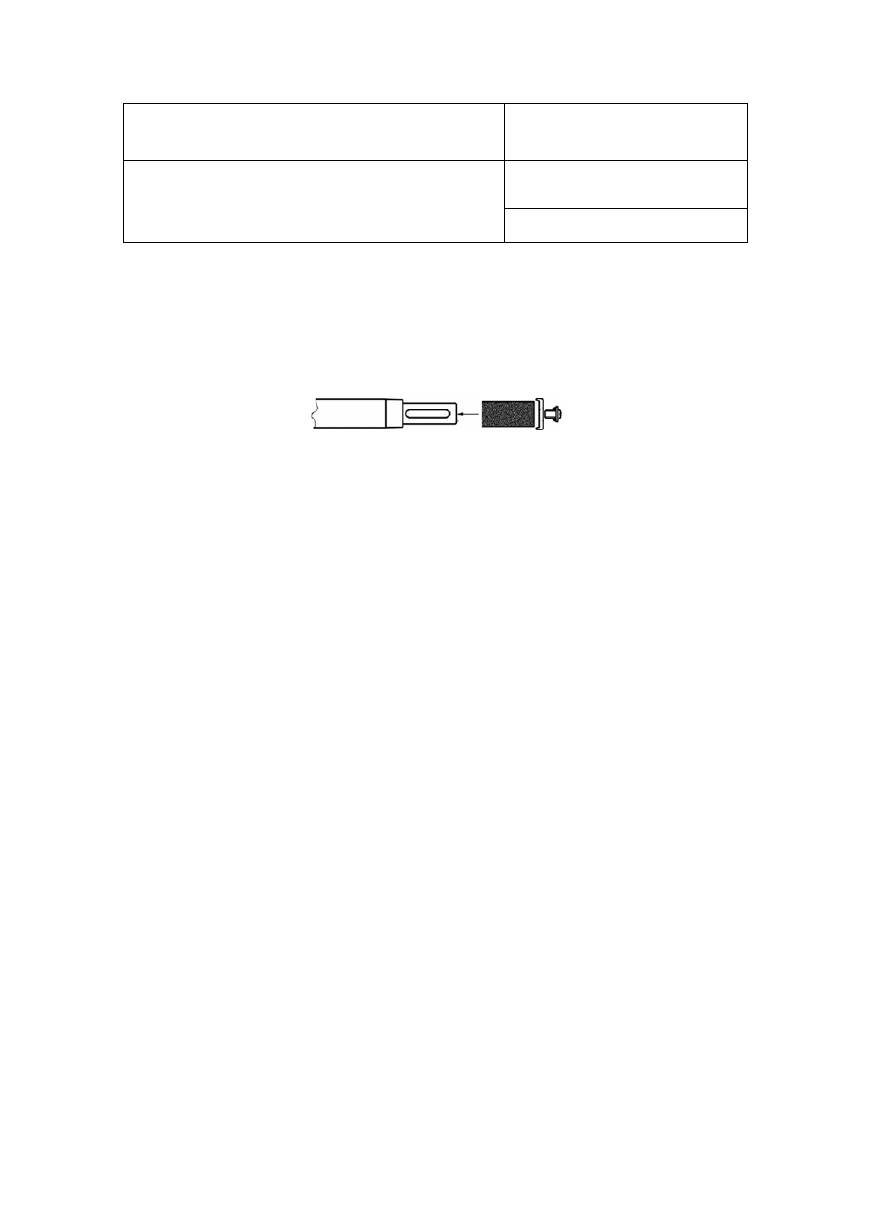
8.1 Cleaning or replacing the dust filter
Depending on the conditions of measurement, the filter should be checked from time to time. Corroded,
discolored or clogged filters should be replaced.
If the probe has a removable cartridge, simply replace the cartridge (leave the metal base on the probe).
If the probe has a plastic slotted cap with a built-in filter element follow these instructions:
1) Unscrew the filter from the probe and pull it straight away, in the alignment of the probe, so as not the
catch the humidity and temperature sensors.
2) Before putting on a new dust filter, check the alignment of both sensors with the probe. The wires that
connect the sensors to the probe are very thin and bend easily. If necessary, correct the alignment by
tapping the sensor very gently with a smooth object such as a small plastic rod. Do not use sharp pliers or
tweezers as this could puncture the sensor and do not pull hard on the sensor.
8.2 Periodic calibration check
Both the Pt 100 RTD temperature sensor and associated electronics are very stable and should not require
any calibration after the initial factory adjustment.
Long term stability of the ROTRONIC Hygromer humidity sensor is typically better than 1 %RH per year. For
maximum accuracy, calibration of the probe should be verified every 6 to 12 months. Applications where the
probe is exposed to contaminants may require more frequent verifications. Calibration and adjustment of the
HC2 probe can be done with either a PC with the HW4 software installed (version 2.1.0 or higher) or with the
HP23 hand-held calibrator. For connecting the HC2 probe to a PC, use any of the following digital adapter
cables AC3001, AC3002 or AC3005 (see document E-M-HC2-accessories).
Procedure for adjusting the HC2 probe with the ROTRONIC HW4 software:
Connect the HC2 probe to the HW4 PC as explained in the HW4 manual E-M-HW4v3-Main
Start HW4 software on the PC and search for the HC2 probe. (HW4 Main Menu Bar > Devices and
Groups > Search for USB masters or Search for RS232 masters or search for Ethernet masters,
depending on the connecting cable).
After finding the HC2 probe with HW4, expand the device tree to see the HC2 probe functions and
select Probe Adjustment.
For further instructions see HW4 manual E-M-HW4v3-A2-001
8.3 Validation of the output signals transmission
If so desired, transmission of the HC2 probe output signals can be validated by using the probe simulator
function. The HW4 software is required to enable and configure this function. When the function is enabled the
probe generates digital and analog signals corresponding to values specified by the user.