E-m-hc2 probes-v1_26, 5mechanical installation – ROTRONIC HC2 User Manual
Page 18
E-M-HC2 Probes-V1_26
Rotronic AG
Bassersdorf, Switzerland
Document code
Unit
HygroClip 2 (HC2) Humidity Temperature
Probes: User Guide
Instruction Manual
Document Type
Page 18 of 31
Document title
© 2009-2013; Rotronic AG E-M-HC2 Probes-V1_26
5
Mechanical installation
Note: the following instructions apply only to the situation where the HC2 probe is fixed installed.
5.1 General guidelines for fixed installation
For best results, please observe the following guidelines:
o
Install the probe at a location where humidity, temperature and pressure conditions are representative of
the environment or process to be measured. Avoid the following: (a) Close proximity of the probe to a
heating element, a cooling coil, a cold or hot wall, direct exposure to sun rays, etc. (b) Close proximity of
the probe to a steam injector, humidifier, direct exposure to precipitation, etc. (c) Unstable pressure
conditions resulting from excessive air turbulence.
o
When installing the probe on a wall, do not place the probe right above a heat producing device of
instrument such as a transmitter or an Ethernet adapter (warm air tends to rise).
o
If possible, choose a location that provides good air movement at the probe: air velocity of at least 1
meter/second (200 ft/ minute) facilitates adaptation of the probe to changing temperature
.
o
When installing the probe through a wall, immerse as much of the probe as possible in the environment to
be measured.
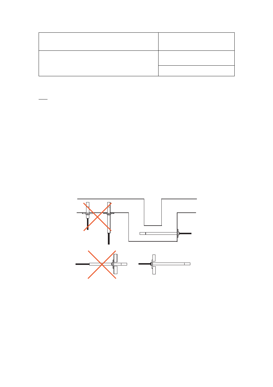
Position the probe so as to prevent the accumulation of condensation water at the level of the sensor leads.
Install the probe so that the probe tip is looking downward. If this is not possible, install the probe horizontally.
Depending on the probe model, a probe holder (mounting flange with a compression fitting) can facilitate
installation through a wall.
Future maintenance can be made easier by providing next to the probe a calibration access orifice. During
maintenance, this permits the insertion of a reference probe (calibrator).The calibration access orifice should
have the same size as the orifice used to install the probe and can be equipped with a probe holder.
OK
OK
OK
OK