Dwyer 8600 User Manual
Page 4
949-1277-3
Page 4
December, 1998
MODEL IDENTIFICATION
Model 8 6 —
—
—
Alarm
0 = No
1 = Yes
Orientation
0 = Vertical
1 = Horizontal
Output 1
1 = SSR
2 = 15 VDC
3 = Relay
5 = Current
Output 2
0 = None
1 = SSR
2 = 15 VDC
3 = Relay
5 = Current
INSTALLATION
Mount the instrument in a location that will not be subject to excessive
temperature, shock, or vibration. All models are designed for mounting in an
enclosed panel.
Select the position desired for the instrument on the panel.
Prepare the panel by cutting and deburring the required opening.
From the front of the panel, slide the instrument through the cut out. The
housing gasket should be against the housing flange before installing.
From the rear of the panel slide the mounting collar over the housing. Hold
the housing with one hand and using the other hand, push the collar evenly
against the panel until the springs are compressed. The ratchets will hold the
mounting collar and housing in place.
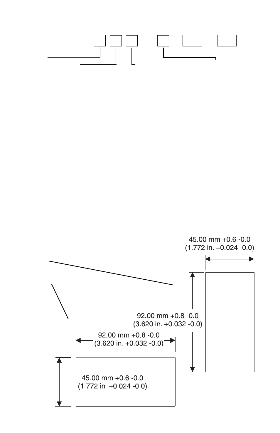
PANEL CUTOUTS
Vertical
Horizontal
OPTIONS