Dwyer DPW User Manual
Page 3
1. UNPACKING THE DPW
1.1 - Inspect Package for External Damage
Your DPW Digital Paddle Wheel was carefully packed in a sturdy cardboard carton,
with antistatic cushioning materials to withstand shipping shock. Upon receipt,
inspect the package for possible external damage. In case of external damage to
the package contact the shipping company immediately.
1.2 - Unpack the DPW meter
Open the carton carefully from the top and inspect for any sign of concealed
shipping damage. In addition to contacting the shipping carrier please forward a
copy of any damage report to your distributor or Dwyer
®
directly. When unpacking
the instrument please make sure that you have all the items indicated on the
Packing List. Please report any shortages promptly.
1.3 - Returning Merchandise for Repair
MAINTENANCE/REPAIR
Upon final installation of the Series DPW, no routine maintenance is required. The
Series DPW is not field serviceable and should be returned if repair is needed. Field
repair should not be attempted and may void warranty.
WARRANTY/RETURN
Refer to “Terms and Conditions of Sales” in our catalog and on our website. Contact
customer service to receive a Return Goods Authorization number before shipping
the product back for repair. Be sure to include a brief description of the problem
plus any additional application notes
2. DPW FLOW METERS TECHNICAL DATA
2.1 - Principles of Operation
DPW liquid flow meters consist of a meter body that is installed in-line in a conduit
system. Inside, between the inlet and the outlet connections is a rotary wheel with
permanent magnets embedded at 180 degrees in paddles.
Fluid flowing through the meter causes the paddle to spin. A magnetic sensor picks
up the frequency of pulses, and the readings are proportional to the liquid flow
taking place. The number of pulses per unit time interval and a K-factor (pulses/unit
of flow) facilitate determining the volumetric rate of flow through the meter.
Additionally, the DPW Flow Meter incorporates a Microcontroller driven circuitry
and non-volatile memory that stores all hardware specific variables. The flow rate
can be displayed in 29 different volumetric or mass flow engineering units. Flow
meter parameters and functions can be programmed remotely via the RS-232/RS-
485 interface or locally via optional LCD/KeyPad. DPW flow meters support various
functions including: two programmable flow totalizers, low, high or range flow and
temperature alarms, 2 programmable optically isolated outputs, 0 to 5 Vdc / 4 to 20
mA analog outputs (jumper selectable) for each process (flow and temperature)
variable, self diagnostic alarm. Optional local 2x16 LCD readout with adjustable
back light provides flow rate, temperature, total volume reading in currently
selected engineering units, diagnostic events indication and feature a password
protected access to the process parameters to ensure against tampering or
resetting.
2.2 - Electrical Connections
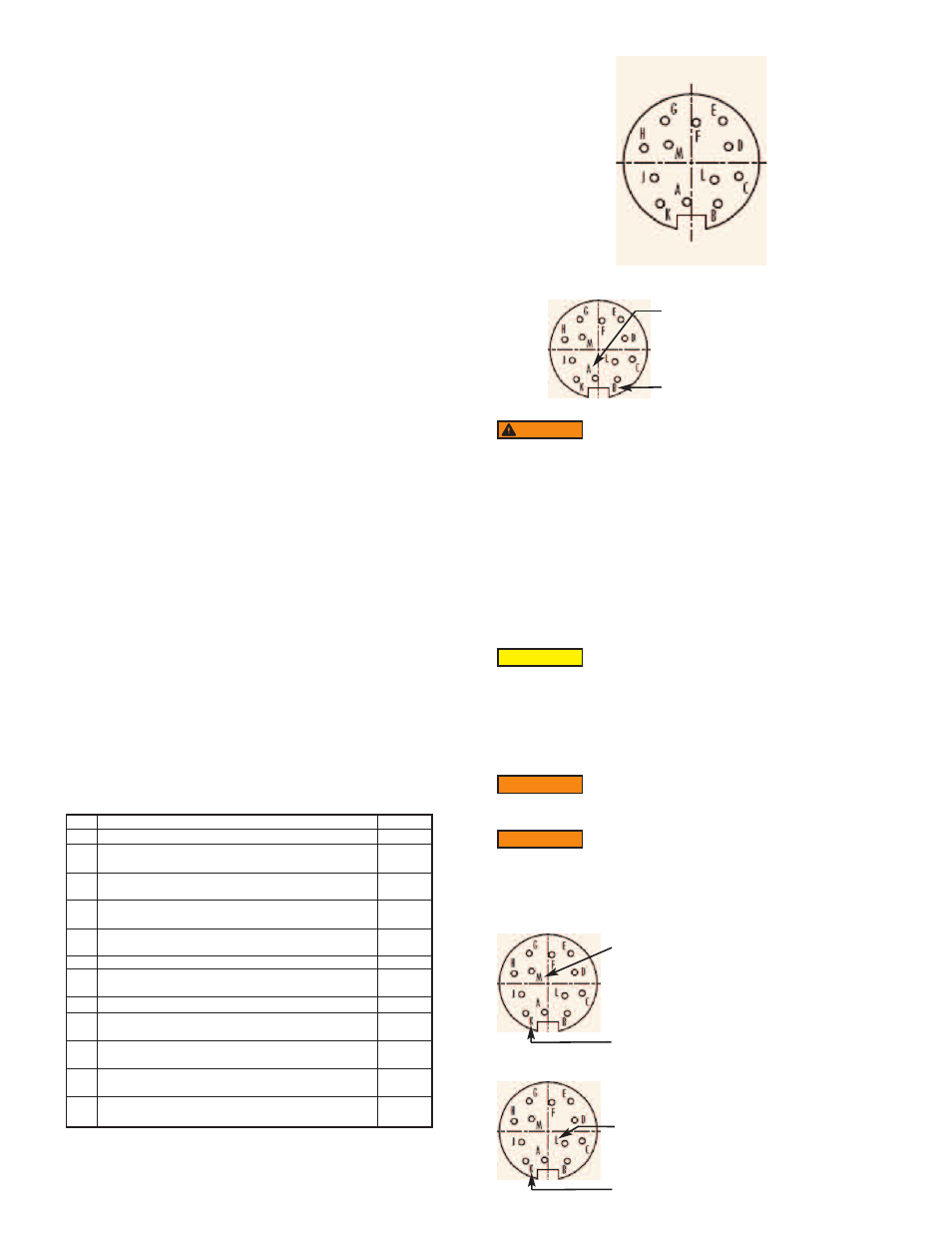
DPW flow meter is supplied with “M16” cylindrical 12 pin connector. Pin diagram is
presented in Figure b-1.
Figure - 1: DPW 12 Pin "M16" Connector Configuration
Pin A -------------
DC Power (+)
Pin B -------------
DC Power (-)
To avoid risk of serious injury or death, make sure power is OFF when connecting
or disconnecting any cables in the system.
The (+) and (-) power inputs are each protected by a 300 mA M (medium time-lag)
resettable fuse. If a shorting condition or polarity reversal occurs, the fuse will cut
power to the flow transducer circuit. Disconnect the power to the unit, remove the
faulty condition, and reconnect the power. The fuse will reset once the faulty
condition has been removed.
Use of the DPW flow meter in a manner other than that specified in this manual or
in writing from Dwyer
®
, may impair the protection provided by the equipment.
2.2.2 Analog Output Signals Connections
DPW series Flow Meters are equipped with either calibrated 0 to 5 or calibrated 4
to 20 mA output signals (jumper selectable). This linear output signal represents
0 to 100% of the flow meter’s full scale range.
Flow 0 to 5 VDC or 4 to 20 mA output signal connection:
Pin M ------------ (+) Plus Flow Analog Output
Pin K ------------ (-) Minus Flow Analog Output
Temperature 0 to 5 VDC or 4 to 20 mA output signal connection (optional):
Pin L ------------(+) Plus Temperature Analog Output
Pin K ------------ (-) Minus Temperature Analog Output
PIN
A
B
C
D
E
F
G
H
J
K
L
M
DPW FUNCTION
Plus Power Supply (+ DC power 11 to 26 Vdc)
Minus Power Supply, (- DC power 11 to 26 Vdc),
Digital Common
Flow Sensor Pulse Output (active), 3.3Vdc 3K min.
load impedance
Digital Communication interface, RS485 (-)
(Optional RS232 TX)
Digital Communication interface, RS485 (+)
(Optional RS232 RX)
Optical Output No.1 Plus (+) (passive)
Optical Output No.1 Minus (-) (passive)
Optical Output No.2 Plus (+) (passive)
Optical Output No.2 Minus (-) (passive)
Common, Analog Signal Ground For Pins L & M,
(4 to 20 mA return)
Temp. Analog Output Plus (+) 0 to 5 Vdc or 4 to 20 mA,
jmp. selectable
Flow Analog Output Plus (+), 0 to 5 Vdc or 4 to 20 mA,
jmp. selectable
TYPE
+Power
-Power,
Common
Output
Only
Input
/Output
Input
/Output
Input
Return
for Pin F
Input
Return
for Pin H
Signal
Common
Output
Only
Output
Only
When connecting the load to the output terminals, do not
exceed the rated values shown in the specifications. Failure to
do so might cause damage to this device. Be sure to check if the wiring and the
polarity of the power supply is correct before turning the power ON. Wiring error
may cause damage or faulty operation.
CAUTION
The 4 to 20 mA current loop output is self-powered (sourcing
type, non-isolated). Do NOT connect an external voltage source
to the output signals.
WARNING
Observe jumper configuration before connecting 4 to 20 mA
current loop load. Failure to make proper jumper configuration
(see Figure 5-1) may cause damage for output circuitry. Do NOT connect an
external voltage source to the output signals.
WARNING
Page 3
Do not apply power voltage above 2 Vdc. Doing so will cause
DPW damage or faulty operation.
WARNING