Dwyer DPW User Manual
Page 22
8. Troubleshooting
8.1 - Common Conditions
Your DPW Flow Meter was thoroughly checked at numerous quality control points
during and after manufacturing and assembly operations. It was calibrated
according to your desired flow and pressure conditions for a given fluid. It was
carefully packed to prevent damage during shipment. Should you feel that the
instrument is not functioning properly, please check for the following common
conditions first:
Are all cables connected correctly? Are there any leaks in the installation? Is the
power supply correctly selected according to requirements? When several meters
are used a power supply with appropriate current rating should be selected. Were
the connector pinouts matched properly? When interchanging with other
manufacturers' equipment, cables and connectors must be carefully wired for
correct pin configurations. Is the pressure differential across the instrument
sufficient?
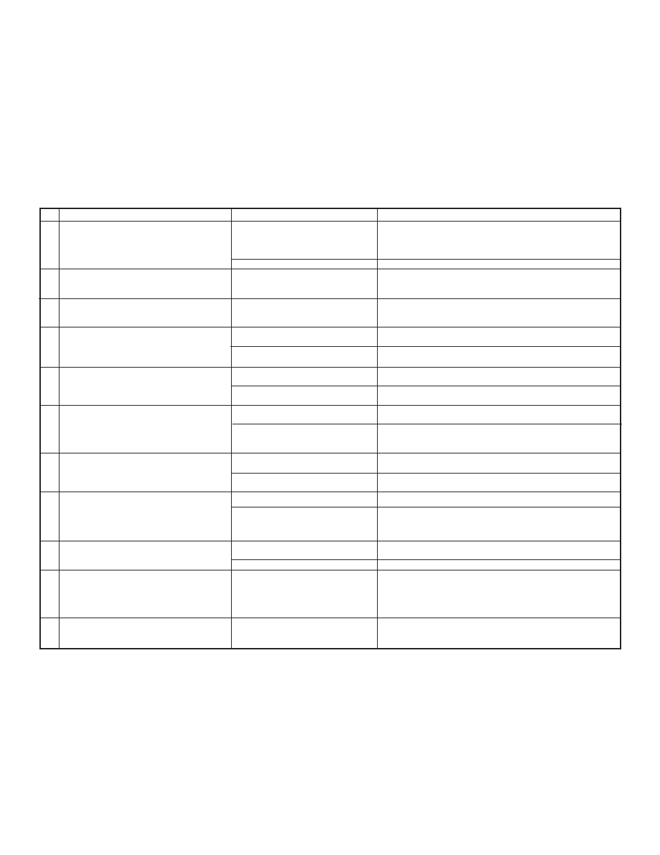
No.
1
2
3
4
5
6
7
8
9
10
11
Indication
LCD display remains blank when unit is powered
up. No response when flow is introduced from
analog outputs 0 to 5 Vdc or 4 to 20 mA.
LCD display reading and/or flow analog output 0
to 5 Vdc signal fluctuate in wide range during
flow measurement.
LCD display reading or /and temperature analog
output 0 to 5 Vdc signal fluctuate in wide range
during flow measurement.
LCD display reading does correspond to the
correct flow range, but 0 to 5 Vdc output signal
does not change (always the same reading or
around zero).
LCD display flow reading and 0 to 5 Vdc output
voltage do correspond to the correct flow range, but
4 to 20 mA output signal does not change (always
the same or reading around 4.0 mA).
LCD display temperature reading and 0 to 5 Vdc
output voltage do correspond to the correct flow
range, but 4 to 20 mA output signal does not
change (always the same or reading around 4.0
mA).
Fluid flows through the DPW meter and Paddle
Wheel is turning, but LCD Display reading and the
flow output voltage 0 to 5 Vdc signal do not respond
to flow.
Fluid flows through the DPW meter and Paddle
Wheel is turning, but LCD Display reading and
the flow output voltage 0 to 5 Vdc signal do not
respond to flow. There is no pulse output signals
from pin C of the 12 pin M16 connector.
The Temperature reading on the LCD and analog 0
to 5 Vdc or 4 to 20 mA is not correct (out of the
device measurement range: -10 to 70C).
The DPW Diagnostic Alarm Event with code
0 – “CPU Temp. High” is active.
The DPW Diagnostic Alarm Event with code F -
“Fatal Error” is active.
Likely Reason
Power supply is bad or polarity is
reversed
PC board is defective.
Flow output 0 to 5 Vdc signal (pin L of
the 12 pin M16 connector) is shorted on
the GND or overloaded.
Temperature output 0 to 5 Vdc signal (pin
M of the 12 pin M16 connector) is
shorted on the GND or overloaded.
Output 0 to 5 Vdc schematic is burned
out or damaged.
Analog flow output scale and offset
variable are corrupted.
External loop is open or load resistance
more than 500 Ω.
Flow output 4 to 20 mA schematic is
burned out or damaged.
External loop is open or load resistance
more than 500 Ω.
Temperature output 4 to 20 mA
schematic is burned out or damaged.
The fluid flow rate is below set Low flow
cut-off value.
Sensor or PC board is defective.
DPW magnetic sensor is defective.
Paddle Wheel magnets are defective.
RTD connector got loose and is not
connected to the PCB board.
RTD sensor is defective.
MCU temperature is too high (overload).
Fatal Error (EEPROM or SRAM
corrupted).
Solution
Measure voltage on pins A and B of the 12 pin M16 connector. If
voltage is out of specified range, then replace power supply with a
new one. If polarity is reversed (reading is negative) make correct
connection.
Return DPW to factory for repair.
Check external connections to pin L of the 12 pin M16 connector.
Make sure the load resistance of the equipment connected to the
flow 0 to 5 Vdc output is more than 1000 Ω.
Check external connections to pin M of the 12 pin M16 connector.
Make sure the load resistance of the equipment connected to the
flow 0 to 5 Vdc output is more than 1000 Ω.
Return DPW to factory for repair.
Restore original EEPROM scale and offset variable or perform analog
output recalibration (see section 5.2).
Check external connections to pins L and K of the 12 pin M16
connector. Make sure the loop resistance is less than 500 Ω.
Return DPW to factory for repair.
Check external connections to pins M and K of the 12 pin M16
connector. Make sure the loop resistance is less than 500 Ω.
Return DPW to factory for repair.
Check settings for Low flow cut-off value and make required
adjustment.
Return DPW to factory for repair.
Replace DPW magnetic sensor.
Replace DPW Paddle Wheel.
Check RTD connector, make sure it is firmly attached to the header
J2 on the PCB.
Replace RTD sensor.
Disconnect power from the DPW. Make sure the ambient
temperature is within specified range (below 70° C). Let the device
cool down for at least 15 minutes. Apply power to the DPW and
check Diagnostic Alarm Event. If overload condition will be indicated
again the unit has to be returned to the factory for repair.
Cycle the power on the DPW. If Diagnostic Alarm Event with code
F indicating again the unit has to be returned to the factory for
repair.
Page 22