Dwyer DPW User Manual
Page 16
4.12.4 - Submenu DAC_A Flow Output
This menu selection provides current value of the DAC register for analog flow
output circuitry.
4.12.5 - Submenu DAC_B Temperature Output
This menu selection provides current value of the DAC register for analog
temperature output circuitry.
4.12.6 - Submenu CPU Temperature
This menu selection provides current value of the PCB and CPU temperature in °C.
4.12.7 - Submenu Raw VCC Reading
This menu selection provides current normalized value of the DC/DC converter
output in counts. The typical values are in the range between 2800 and 3200
counts.
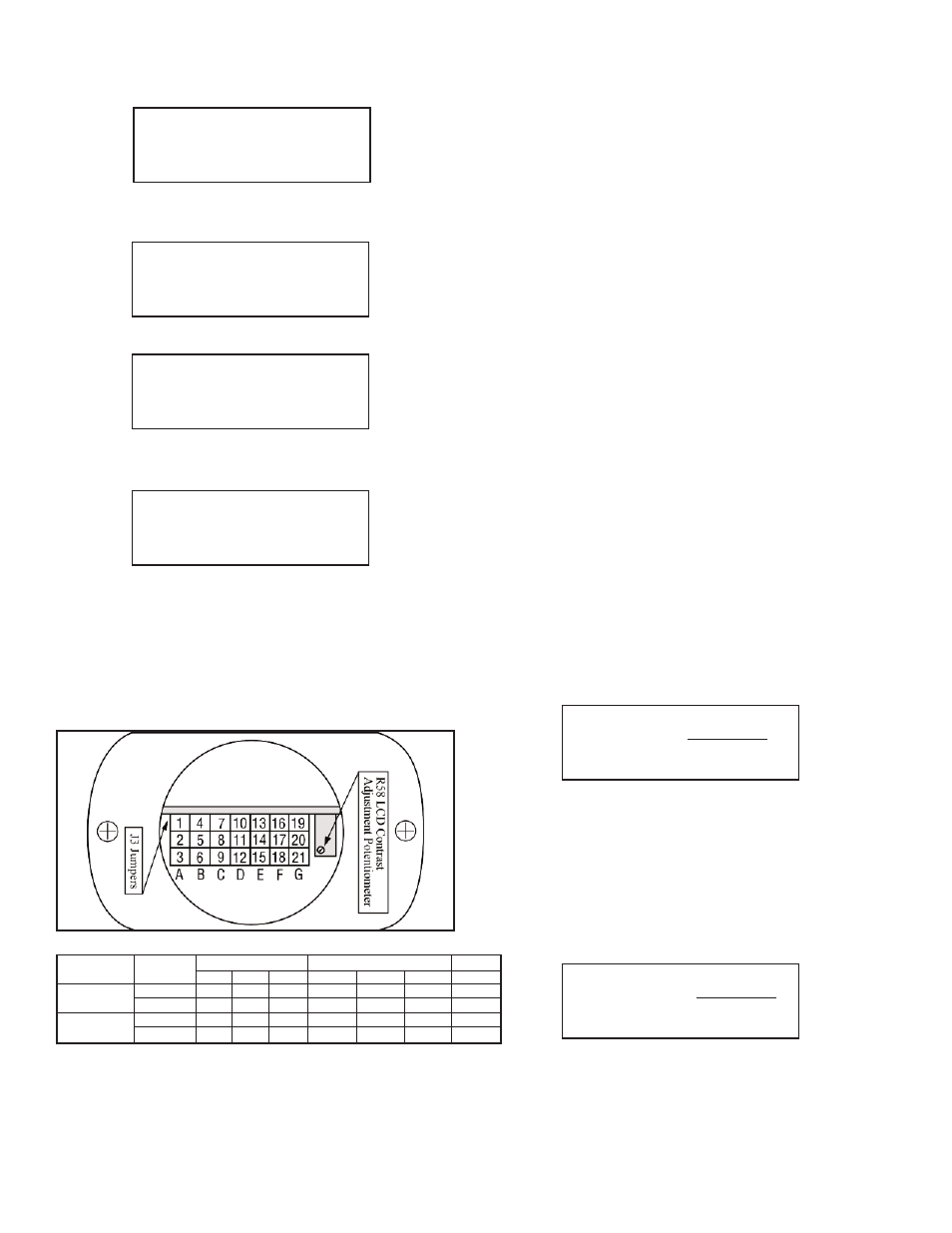
5. Analog Output Signals
5.1 - Analog Output Signals Configuration
DPW series Flow Meters are equipped with calibrated 0 to 5 Vdc and/or 4 to 20 mA
output signals for flow and temperature* process variables. The set of the jumpers
(J3A, J3B, J3C, J3D, J3E, J3F) located on the top of the flow meter, inside of the
maintenance access window (see Figure 5-1 “DPW configuration jumpers”) are
used to switch between 0 to 5 Vdc or 4 to 20 mA output signals. Jumpers J3A, J3B,
J3C are used to set flow analog output type and jumpers J3D, J3E, J3F are used
to set temperature* analog output type (see Table 5-1). Jumper J3G is used to
configure RS-485 termination resistor (by default is off).
5.2 - Analog Output Signals calibration
Note: The analog output available on the DPW Flow Meter was calibrated at the
factory for the specified fluid and full scale flow range (see the device’s front label).
There is no need to perform analog output calibration unless the EEPROM IC was
replaced or offset/span adjustment is needed. Any alteration of the analog output
scaling variables in the EEPROM table will VOID calibration warranty supplied with
instrument.
Note: It is recommended to use the Dwyer Instruments, Inc. supplied calibration
and maintenance software for analog output calibration. This software includes an
automated calibration procedure which may radically simplify calculation of the
offsets and spans variables and, the reading and writing for the EEPROM table.
The DPW analog output calibration involves calculation and storing of the offset
and span variables in the EEPROM for each available output. The 0 to 5 Vdc output
has only scale variable and 20 mA output has offset and scale variables. The
following is a list of the EEPROM variables used for analog output computation:
Analog Flow Output variables
Index Name
Description
39
FoutScaleV
- DAC 0 to 5 Vdc Flow Analog Output Scale
41
FoutScale_mA
- DAC 4 to 20mA Flow Analog Output Scale
42
FoutOffset_mA
- DAC 4 to 20mA Flow Analog Output Offset
Analog Temperature Output variables*
Index Name
Description
43
ToutScaleV
- DAC 0 to 5 Vdc Temperature Analog Output Scale
45
ToutScale_mA
- DAC 4 to 20mA Temperature Analog Output Scale
46
ToutOffset_mA - DAC 4 to 20mA Temperature Analog Output Offset
5.2.1 - Initial Setup
Power up the DPW Flow Meter for at least 15 minutes prior to commencing the
calibration procedure. Make sure absolutely no flow takes place through the meter.
Establish digital RS-485/RS-232 communication between PC (communication
terminal) and DPW. The commands provided below assume that calibration will be
performed manually (w/o Dwyer
®
supplied calibration and maintenance software)
and the device has RS-485 address 11. If Dwyer
®
supplied calibration and
maintenance software is used, skip the next section and follow the software
prompts.
Enter Backdoor mode by typing: !11,MW,1000,1[CR]
Unit will respond with: !11,BackDoorEnabled: Y
Disable DAC update by typing: !11,WRITE,4,Y[CR]
Unit will respond with: !11,DisableUpdate: Y
5.2.2 - Flow 0 to 5 VDC analog output calibration
1. Install jumpers J3A, J3B and J3C on the PC board for 0 to 5 Vdc output
(see Table 5-1).
2. Connect a certified high sensitivity multi meter set for the voltage measurement
to the pins M (+) and K (-) of the DPW 12 Pin "M16" connector.
3. Write 4000 counts to the DAC_A channel: !11,WRITE,0,4000[CR]
4. Read voltage with the meter and calculate FOutScaleV value:
5. Save FOutScaleV in to the EEPROM: !11,MW,39,X[CR]
Where: X – the calculated FoutScaleV value.
5.2.3 Flow 4 to 20 mA analog output calibration
1.
Install jumpers J3A, J3B and J3C on the PC board for 4-20 mA output
output (see Table 5-1).
2.
Connect a certified high sensitivity multimeter set for the current
measurement to pins M (+) and K (-) of the DPW 12 Pin "M16" connector.
3.
Write 4000 counts to the DAC_A channel: !11,WRITE,0,4000[CR]
4.
Read current with the meter and calculate FoutScale_mA value:
5.
Write zero counts to the DAC_A channel: !11,WRITE,0,0CR]
6.
Read offset current with the meter and calculate FoutOffset_mA value:
7.
Save FoutScale_mA in to the EEPROM: !11,MW,41,Y[CR]
Save FoutOffset_mA in to the EEPROM: !11,MW,42,Z[CR]
Where: Y – the calculated FoutScale_mA value.
Z – the calculated FoutOffset_mA value.
DAC_A Output (F)
3125 Counts
DAC_B Output (T)
1358 Counts
CPU Temperature
35.8 C
Raw VCC Reading
3065 Counts
Figure 5-1 DPW Configuration Jumpers
Analog
Output
RS-485 220 Ω
Termination
Resistor
Function
0 to 5 VDC
4 to 20 mA
OFF
ON
J3A
2 to 3
1 to 2
J3B
5 to 6
4 to 5
J3C
8 to 9
7 to 8
J3D
11 to 12
10 to 11
J3E
14 to 15
13 to 14
J3F
17 to 18
16 to 17
J3G
20 to 21
19 to 20
Analog Flow Output
Analog Temp. Output*
RS-485
FoutScaleV=
20000
Reading[V]
FoutScale_mA =
4000
Reading[mA]
Page 16