Badger Meter SRD/SRI Valve Positioners User Manual
Page 22
Preparing the Actuator
Screw the carrier bolt to the stem connector and lock it by means of a counter nut
A carrier bolt with an adjustable length is used to be able to screw on various coupling pieces
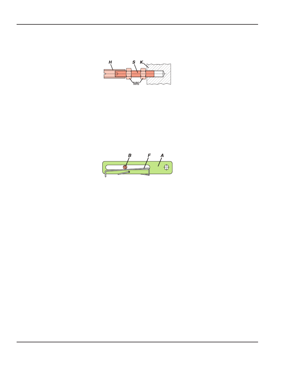
Figure 4: Carrier bolt
It consists of a stud S, which is screwed into the coupling piece K (with 3 mm Allen key) and locked with a lock nut M6 The
threaded sleeve H is screwed onto it and locked with a lock nut M6 Make sure that the bolt is adjusted to the right length!
Fasten the mounting bracket to the left side of the yoke For a cast yoke use a screw M8 x 30, for a pillar yoke use two U-bolts
and four nuts
Mounting of the Positioner
Fasten the positioner to the mounting bracket using two spring washers and two screws M8 x 80
Note, the carrier bolt B is in the slot of the feedback lever A and the compensating spring F touches the carrier bolt
Figure 5: Feedback lever
For optimum use of the positioner operating range, it is recommended that the arrangement is adjusted according to the
following procedure before fixing At an actuator position in the middle of travel range, the feedback lever position should be
perpendicular to the actuator stem and the angle range should be between −10…10° and −45…45°
Fasten the positioner to the mounting bracket so that a suitable angle range is selected
It is recommended that the pneumatic and electrical connections are made after adjusting the position
Mounting to Actuators
Page 22
August 2014
POS-UM-00010-EN-03