Badger Meter M-Series M4000 User Manual
Page 7
7
6. The ambient temperature range surrounding a remote
junction box mounted to the detector is -4°F to 248°F
(-20°C to 120°C.)
Pipelines and Fluid Flow
Pipeline and fl uid fl ow conditions that should be avoided:
1. Do not install the meter where extreme pipe vibrations
exist. If vibrations are present, secure piping before
and after the meter with appropriate pipe supports. If
vibrations can’t be restrained, consider mounting the
amplifi er remotely.
2. Avoid installing the detector close to pipeline valves,
fi ttings or impediments that can cause fl ow disturbances.
3. For detectors with PTFE liners, avoid installing the
detector on suction sides of pumps.
4. Avoid installing the detector on outlet sides of piston
or diaphragm pumps. Pulsating fl ow can affect meter
performance.
5. Avoid locations near equipment producing electrical
interference such as electric motors, transformers, variable
frequency, power cables, etc.
6. Verify both ends of the signal cables are securely
fastened.
7. Place power and signal cables in separate conduit.
8. Place the meter where there is enough access for
installation/maintenance purposes.
Meter Orientation
Mag meters can operate accurately in any pipeline
orientation and can measure volumetric fl ow in forward and
reverse directions.
NOTE: A Forward Flow direction arrow is printed on the
detector label.
Vertical Placement
Mag meters attain optimal performance when placed
vertically, with liquid fl owing upward and meter electrodes in
a closed, full pipe.
Vertical placement allows the pipe to remain completely full,
even in low fl ow, low pressure applications and it prevents
any solids build-up or sediment deposit or accumulation on
the liner and/or electrodes.
NOTE: Carefully observe the “Forward Flow” label on the
meter body and install the meter accordingly.
Horizontal Placement
In a horizontal piping orientation, mount the detector to
piping with the fl ow measuring electrode axis in a horizontal
plane (3 and 9 o’clock).
This arrangement prevents solids build-up or sediment
deposit or accumulation on the electrodes.
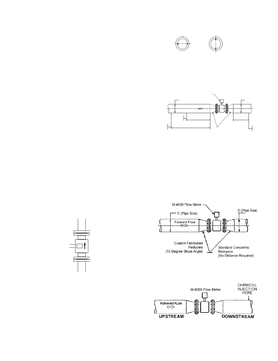
Electrode
Plane
RIGHT
Electrode
Plane
WRONG
Straight Pipe Requirements
Suffi cient straight pipe runs are required at the detector inlet
and outlet for optimum meter accuracy and performance. An
equivalent of three (3) diameters of straight pipe is required on
the inlet (upstream) side. Two (2) diameters are required on
the outlet (downstream) side.
FORWARD FLOW
MINIMUM STRAIGHT PIPE
MINIMUM STRAIGHT PIPE
ELBOW
TEE
GATE VALVE
(FULLY OPEN)
MINIMUM STRAIGHT PIPE
CHECK VALVE
GLOBE VALVE
BUTTERFLY VALVE
PUMP
ELBOW
TEE
ANY VALVE
M-4000 Mag FLOWMETER
3 x D
7 x D
2 x D
D (Pipe Size)
D (Pipe Size)
MINIMUM PIPING REQUIREMENT
STANDARD CONCENTRIC
REDUCERS
(NO DISTANCE REQUIRED)
Pipe Reducer Requirements
With pipe reducers a smaller size meter can be mounted in
larger pipelines. This arrangement may increase low fl ow
accuracy.
There are no special requirements for standard, concentric,
pipe reducers.
Custom fabricated pipe reducers must have an approximate
slope angle of 15 degrees to minimize fl ow disturbances
and excessive loss of head. If this is not possible, install the
custom pipe reducers as if they were fi ttings and install the
amount of straight pipe stated previously.
Chemical Injection Applications
For water line applications with a chemical injection point,
install the meter upstream of the injection point. This
eliminates any meter performance issues.
If a meter must be installed downstream of a chemical
injection connection, the recommended distance between