Badger Meter M-Series M4000 User Manual
Page 13
13
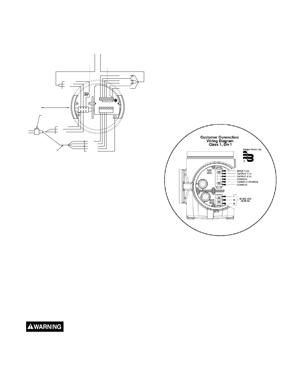
Coil Wiring in Amplifi er Junction Box
To connect the coil wires in the amplifi er junction box:
1. Strip the cable jacket back 2 inches (50mm).
2. Strip the 2 wires back ¼ inch (6mm).
3. Connect the wires to the compression style screw
terminals of the amplifi er junction box.
SHIELD
RED
GREEN
BLACK
WHITE
BELDEN 9155 OR EQUIVALENT
SHIELD
BELDEN 8770
OR
EQUIVALENT
RED
CLEAR
SEAL
SHIELD
RED
CLEAR
FOLLOW NEC 504
BLACK
WHITE
GREEN
PINK
C1 C2 SHLD
E1
SHLD
+5V
E1
SHLD
E2
EP
SHLD
-5V
+5V
-5V
EP
E2
SHLD
CONDUIT SEAL LOCATED AT
ENCLOSURE ENTRY PER 505.18
FOR ZONE 1 INSTALLATIONS
COIL WIRES
Red to terminal labeled –
C1
Clear to terminal labeled –
C2
4. Connect conduit to junction box. Use a NEMA 4X ½ inch
NPT fi tting.
5. Install protective plastic cover over terminal blocks.
6. Attach the amplifi er junction box chamber cover.
OUTPUT WIRING
The Badger
®
M-4000 Meter converts liquid fl ow into
electrical signal(s). With proper output wiring and amplifi er
programming, the signal(s) are sent to, and used by,
processing equipment used in operations or other
procedures.
NOTE: Output wires and terminals are the same for meter
mount or remote mount meters
Output wiring requires 18 to 22 AWG maximum, shielded
wire (not supplied). Signal wire insulation temperature class
should exceed the maximum temperature where installed
(typical, 185°F, 85°C).
Use conduit and conduit fi ttings (not supplied) rated for Class
I, Div 1 hazardous locations.
Output Wire Connections
·
Properly trained personnel must perform all
installation and/or repair procedures.
·
Disconnect power to the unit before attempting any
installation or maintenance.
To connect control signal wires:
1. Remove the connections chamber cover. If necessary,
use a strap wrench.
2. Remove the two terminal block wire port access screws.
3. Connect output wires to processing equipment.
4. Group and place output wires in conduit. Position conduit
at amplifi er terminal block wire ports.
5. Connect conduit to control output signal wires ports.
6. Run output wires through wire ports, into amplifi er
terminal chamber.
7. Strip output wires back ¼ inch (6mm).
8. Connect output wires to terminals (see below).
NOTE: Use twisted pair shielded wire for all output wiring.
Belden #1266A or equivalent.
Amplifi er Output Wire Terminal Block Connections:
Reference Control Signal Wiring Diagrams on next two pages.