Badger Meter M-Series M4000 User Manual
Page 31
31
5.
Replace the fuse.
6.
Reverse steps 1 to 3 to assemble the unit.
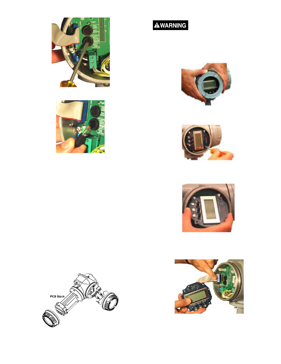
Amplifi er Printed Circuit Board (PCB) Stack
Replacement
All M-4000 mag meters operate through printed circuit
boards (PCBs) housed in the amplifi er. The PCBs are
grouped in a stack located behind the display/control card in
the display/programming chamber.
Because PCBs are complex circuits, with all meter functions
enabled through multiple links and layers, determining the
exact board and circuit that is causing a system problem is
diffi cult and usually requires test equipment.
Should a meter problem occur:
1. Call Badger Meter at 877-243-1010, and discuss the
problem with a Technical Support Specialist.
2. If the problem appears to originate in a PCB, it will be
recommended that the entire PCB stack be removed and
returned to Badger Meter.
PCB Stack in Amplifi er
REMOVE PCB STACK
Disconnect main power to the unit before attempting any
device maintenance.
1.
Remove display/programming chamber cover. Turn the
cover counterclockwise to remove it from the amplifi er. If
necessary, use a strap wrench.
2.
Remove 2 display card screws and washers. Place in
storage for reuse.
3.
Tilt display card up/out approximately 45 degrees at the
holding clips.
4.
Gently pull card down and out from between holding clips.
5.
Disconnect display card plug from left side of PCB
display.
6.
Disconnect the Power, Coil, Electrode and I-O plugs and
harnesses from the PCB interconnect card.