Amplifier specifications – Badger Meter M-Series M4000 User Manual
Page 29
29
SPECIFICATIONS
Power Supply: 85-265VAC, 45-65Hz
Power Consumption: 20W
Accuracy: ± 0.25% of rate for velocities greater than
1.64 ft/s (0.50 m/s)
± 0.004 ft/s (± 0.001 m/s) for velocities less
than 1.64 ft/s (0.50 m/s)
Repeatability: 0.1% of rate
Flow Range: 0.10 to 39.4 ft/s (0.03 to 12 m/s)
Fluid Conductivity: Min. 5.0 micromhos/cm
Flow Direction: Unidirectional or bidirectional
(programmable)
Totalization: 3 separate displayable totalizers – 10
digits (programmable - forward, reverse and net)
Analog Outputs: 0-10mA, 0-20mA, 4-20mA
(programmable and scalable)
Voltage sourced (18VDC) – isolated
Max. loop resistance = 750 Ω
Frequency Output: Open Collector – Max. full scale
fl ow = 10Khz
Digital Outputs:
(2) Open collector, (programmable – scaled
pulse, fl ow alarm, status, or frequency output)
Max. 24VDC, 0.5W
(2) AC solid state relay (programmable – fl ow
alarm or status). Max. [email protected]
Pulse Width: Open collector, 5ms to 1 second
(programmable) or automatic 50% duty cycle
Min-Max Flow Alarm: Open collector or solid state
relay (programmable – 0 to 100% of fl ow)
Empty Pipe Detection: Field tunable for optimum
performance based on specifi c application
Excitation Frequency: Programmable - 3.75Hz, 7.5Hz
or
15Hz
Auxiliary Input: Max. 24VDC (programmable – positive
zero return, external totalizer reset or preset
batch start)
Noise Dampening: 1 to 30 seconds (programmable)
Units of Measure: U.S. gallons, imperial gallons, million
gallons per day, cubic feet, cubic meters, liters,
oil barrels, pounds, ounces, acre feet
Low Flow Cut-Off: 0 to 100% of full scale
(programmable)
Zero-Point Stability: Automatic correction
LC Display: 4 lines X 16 character alphanumeric – back
light, actively displays 3 totalizer values, fl ow
rate, alarm status, output status, error / diagnostic
messages
Programming: Internal 3 button or external magnetic
wand
Galvanic Separation: £ 500 volts
Electrical Classifi cation:
FM approved for Class I, Div I, Groups B-D
Class II, Div 2, Groups E, F and G - CSA Certifi ed
Housing: Amplifi er enclosure and remote junction
enclosure: cast aluminum (powder coated paint)
Housing Rating: Amplifi er enclosure and remote
junction enclosure – NEMA 4X (IP66)
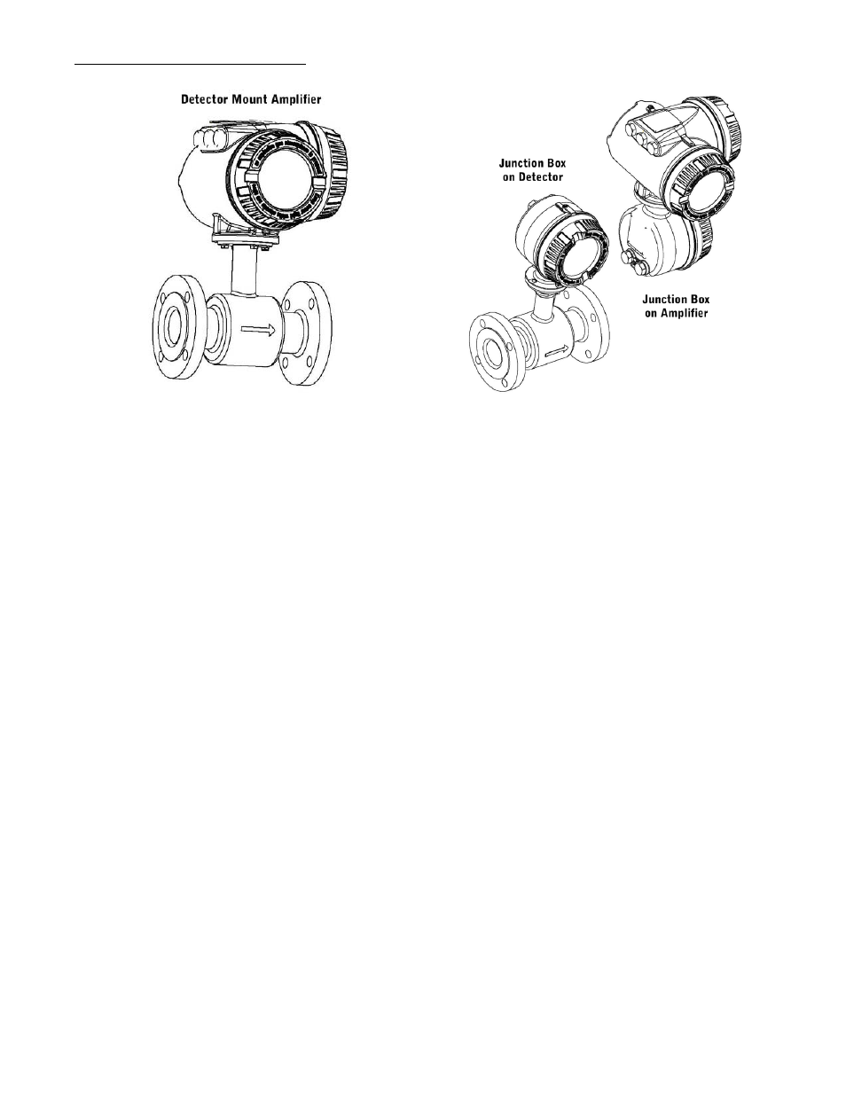
Mounting: Direct detector mount or remote wall mount –
bracket included. (for remote mount, max. cable
distance = 100 ft (30M)
Field Wiring Entry Ports: (3) ½ “ NPT, internal thread
Ambient Temperature: -20°F to 122°F (-29°C to 50°C)
Communication: RS232C serial, standard ANSI terminal
compatible data stream
AMPLIFIER SPECIFICATIONS