Analog output wiring diagrams – Badger Meter M-Series M4000 User Manual
Page 14
14
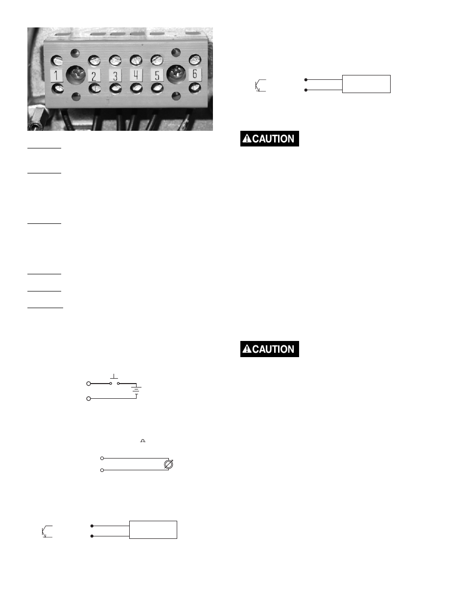
Terminal 1 Input 1 (+) - Input -
Functions: reset, positive zero return.
Terminal 2 Output 1 (+) Programmable passive output to
Badger
®
external counter.
Functions: forward pulse, frequency output, preset output,
fl ow set point, error alarm, fl ow direction
Active Output to external counter.
Terminal 3 Output 1 (+) ProgrammableTransistor Output
(open collector) - Passive Output to Badger external counter.
Functions: forward pulse, AMR pulse, fl ow set point, error
alarm, empty pipe, fl ow direction.
Active Output to external counter.
Terminal 4 Common fi eld ground.
Terminal 5 Analog Output.
Terminal 6 Ground from external counter device connected
to terminal 5.
Auxiliary Input Wiring Diagram
Function: Reset
Positive
Zero
Return
Input 1 (+)
1
Common 4
5-24VDC
_____________________________________________
Analog Output Wiring Diagrams
• Analog Output (Loop voltage = 18VDC Sourced, 750 MAX)
Function: 4-20mA
0-20mA
0-10mA
mA Analog Output (+) 5
Common 6
_____________________________________________
Functions:
Forward (only) Pulse
AMR
Pulse
Flow
Set
Point
Error
Alarm
Empty
Pipe
Flow
Direction
Output 1 (+)
3
Common 4
02
01
+
—
External Counter
Badger Meter ER8
or AMR Device
}
Programmable
• Output 1
Transistor Output (open collector)
24VDC
Max
.5W
Max
Passive Output Wiring
_____________________________________________
• Output 2
Transistor Output (open collector)
24VDC
Max
.5W
Max
Passive Output
Functions:
Reverse (only) Pulse
Frequency
Output
Preset
Output
Flow
Set
Point
Error
Alarm
Flow
Direction
}
Programmable
Output 2 (+)
5
Common 6
02
01
+
—
External Counter
Badger Meter ER8
or AMR Device
External Disconnect
Position this device in an accessible location.
Position and identify the disconnect device so as to provide
safe and easy operation.
Label the disconnect device as being for the Mag Meter.
Install an external disconnect switch or circuit breaker that
meets local standards.
AC Power Wiring
For AC power use three wire, sheathed, cable with cable
diameter of 18 AWG (not supplied).
AC wire insulation temperature class must not exceed the
maximum ambient temperature of its location (typical, 185°F,
85°C).
Use conduit and conduit fi ttings (not supplied) that are rated
for Class I, Div 1 hazardous locations. To maintain a NEMA
4X rating, use watertight fi ttings that are rated NEMA 4X or
better.
To prevent accidents connect main power only after all
other wiring has been completed.