Badger Meter M-Series M4000 User Manual
Page 12
12
NOTE: Plastic cover must be reattached to maintain
hazardous location rating.
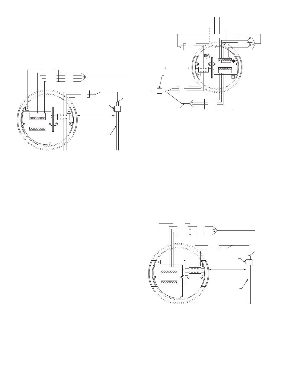
3. Strip the cable jacket back 2 inches (50mm).
4. Strip the 4 wires back ¼ inch (6mm).
5. Thread wires through the proper cable access.
Connect the wires to the compression style screw
terminals of the Detector Junction Box.
RED
SHIELD
CLEAR
SHIELD
18 AWG
OR 1mm2
BELDEN 9155 OR EQUIVALENT
BELDEN 8770
OR
EQUIVALENT
18/20 AWG
OR 1.0 / 0.5 mm 2
20 AWG
18 AWG
20 AWG
18 AWG
FOR ZONE 1 INSTALLATION
CONDUIT SEAL LOCATED AT
ENCLOSURE ENTRY PER 505.18
SEAL
FOR CLASS 1 DIV 1 OR 2 FOLLOW
NEC 501.4 AND 501.5.
FOR CLASS 1 ZONE 1 FOLLOW
NEC. 505.15 AND 505.18
EP
E2
SHLD
SHLD
E1
SHLD C2 C1
+5V
-5V
EP
E2
SHLD
SHLD
E1
WHITE
BLACK
GREEN
RED
+5V
-5V
ELECTRODE WIRES
Red to terminal labeled -
E1
Green to terminal labeled -
SHLD
Black to terminal labeled -
E2
White to terminal labeled -
EP
Cable length, between Junction Boxes, may be up to 100
feet (30M).
6. Run cable and conduit to Amplifi er junction box.
Electrode Wiring in Amplifi er Junction Box
To connect the electrode wires in the Amplifi er Junction Box:
1. Unscrew the amplifi er junction box chamber cover. If
necessary, use a strap wrench.
2. Remove the protective plastic cover to access the
terminal block screws.
NOTE: Plastic cover must be reattached when wiring is
complete to maintain hazardous location rating.
3. Strip the cable jacket back 2 inches (50mm).
4. Strip the 4 wires back ¼ inch (6mm).
5. Thread wires through the proper cable access. Connect
the wires to the compression style screw terminals of the
Amplifi er Junction Box.
SHIELD
RED
GREEN
BLACK
WHITE
BELDEN 9155 OR EQUIVALENT
SHIELD
BELDEN 8770
OR
EQUIVALENT
RED
CLEAR
SEAL
SHIELD
RED
CLEAR
FOLLOW NEC 504
BLACK
WHITE
GREEN
PINK
C1 C2 SHLD
E1
SHLD
+5V
E1
SHLD
E2
EP
SHLD
-5V
+5V
-5V
EP
E2
SHLD
CONDUIT SEAL LOCATED AT
ENCLOSURE ENTRY PER 505.18
FOR ZONE 1 INSTALLATIONS
ELECTRODE WIRES
Red to terminal labeled -
E1
Green to terminal labeled -
SHLD
Black to terminal labeled -
E2
White to terminal labeled -
EP
Coil Wiring in Detector Chamber
To connect coil wires in the Detector chamber:
1. Lay out the cable and conduit between the Detector
Junction Box and the Amplifi er Junction Box. Use Belden
#8770 cable or equivalent for coils.
NOTE: Plastic cover must be reattached to maintain
hazardous location rating.
2. Strip the cable jacket back 2 inches (50mm).
3. Strip the 2 wires back ¼ inch (6mm).
4. Thread wires through the proper cable access. Connect
the wires to the compression style screw terminals of the
detector chamber.
RED
SHIELD
CLEAR
SHIELD
18 AWG
OR 1mm2
BELDEN 9155 OR EQUIVALENT
BELDEN 8770
OR
EQUIVALENT
18/20 AWG
OR 1.0 / 0.5 mm 2
20 AWG
18 AWG
20 AWG
18 AWG
FOR ZONE 1 INSTALLATION
CONDUIT SEAL LOCATED AT
ENCLOSURE ENTRY PER 505.18
SEAL
FOR CLASS 1 DIV 1 OR 2 FOLLOW
NEC 501.4 AND 501.5.
FOR CLASS 1 ZONE 1 FOLLOW
NEC. 505.15 AND 505.18
EP
E2
SHLD
SHLD
E1
SHLD C2 C1
+5V
-5V
EP
E2
SHLD
SHLD
E1
WHITE
BLACK
GREEN
RED
+5V
-5V
COIL WIRES
Red to terminal labeled –
C1
Clear to terminal labeled –
C2
5. Connect conduit to junction box. Use a NEMA 4X ½ inch
NPT fi tting.
6. Install protective plastic cover over terminal blocks.
7. Attach detector chamber cover.
Cable length between Junction Boxes may be up to 100 feet
(30M).