Input signals – Alicat LC Series Liquid Flow Controller User Manual
Page 13
13
INPUT SIGNALS
Analog Input Signal
Apply analog input to Pin 4 as shown on page 12.
For 6 Pin Locking Connector, DB9 and DB15 Pin-outs see pages 58 to 70.
For PROFIBUS Pin-outs see pages 56.
Standard 0-5 Vdc is the standard analog input signal. Apply the 0-5 Vdc input
signal to pin 4, with common ground on pin 8.
Opti onal 0-10 Vdc: If specifi ed at ti me of order, a 0-10 Vdc input signal can be
applied to pin 4, with common ground on pin 8.
Opti onal 4-20 mA: If specifi ed at ti me of order, a 4-20 mA input signal can be
applied to pin 4, with common ground on pin 8.
NOTE: This is a current sinking device. The receiving circuit is essenti ally a 250
ohm resistor to ground.
NOTE: 4-20mA output requires at least 15 Vdc power input.
CAUTION! D� ��� ������� ���� ������ �� “���� �������’”
�������, �� ���� ���� ������� �������� �� ��� ��������� ��� ����
��� ��������. I� ��� ���� ��������� ���� �������� ���� �������
�������, ������ ��� � ������ �������� ��� � �������� ����� ������.
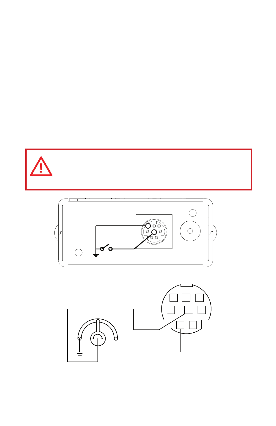
Gauges: A remote tare can be achieved by momentarily grounding pin 4 to tare.
7
6
5
4
3
2
1
8
5.12 Vdc
50 KOhm
Potentiometer
0-5 Vdc
Controllers: A simple method for providing set-point to controllers
4
8