Power and signal connections, Not connected, Caution! d� ��� ������� ����� �� ���� 1 ������� 6 – Alicat LC Series Liquid Flow Controller User Manual
Page 12
12
POWER AND SIGNAL CONNECTIONS
Power can be supplied to your meter/controller through either the power jack or
the 8 pin Mini-DIN connector.
An AC to DC adapter which converts line AC power to DC voltage and current as
specifi ed below is required to use the power jack.
A 2.1mm, positi ve center, 7-30 Vdc AC/DC adapter rated for at least 100 mA is
required to use the adapter jack in a L-Series meter.
A 2.1mm, positi ve center, 12-30 Vdc AC/DC adapter rated for at least 250 mA is
required to use the adapter jack in a LC-Series controller.
A 2.1mm, positi ve center, 24-30 Vdc AC/DC adapter rated for at least 500 mA is
required to use the adapter jack in a LCR-Series controller.
NOTE: 4-20mA analog output requires at least 15 Vdc.
It is common to mistake Pin 2 (labeled 5.12 Vdc Output) as the standard 0-5 Vdc
analog output signal. In fact Pin 2 is normally a constant 5.12 Vdc that refl ects the
system bus voltage and can be used as a source for the set-point signal.
For 6 Pin Locking Connector, DB9 and DB15 Pin-outs see pages 58 to 70.
For PROFIBUS Pin-outs see pages 56.
Electrical Connecti ons and Basic Wiring
htt p://www.alicat.com/support/instructi onal-videos/
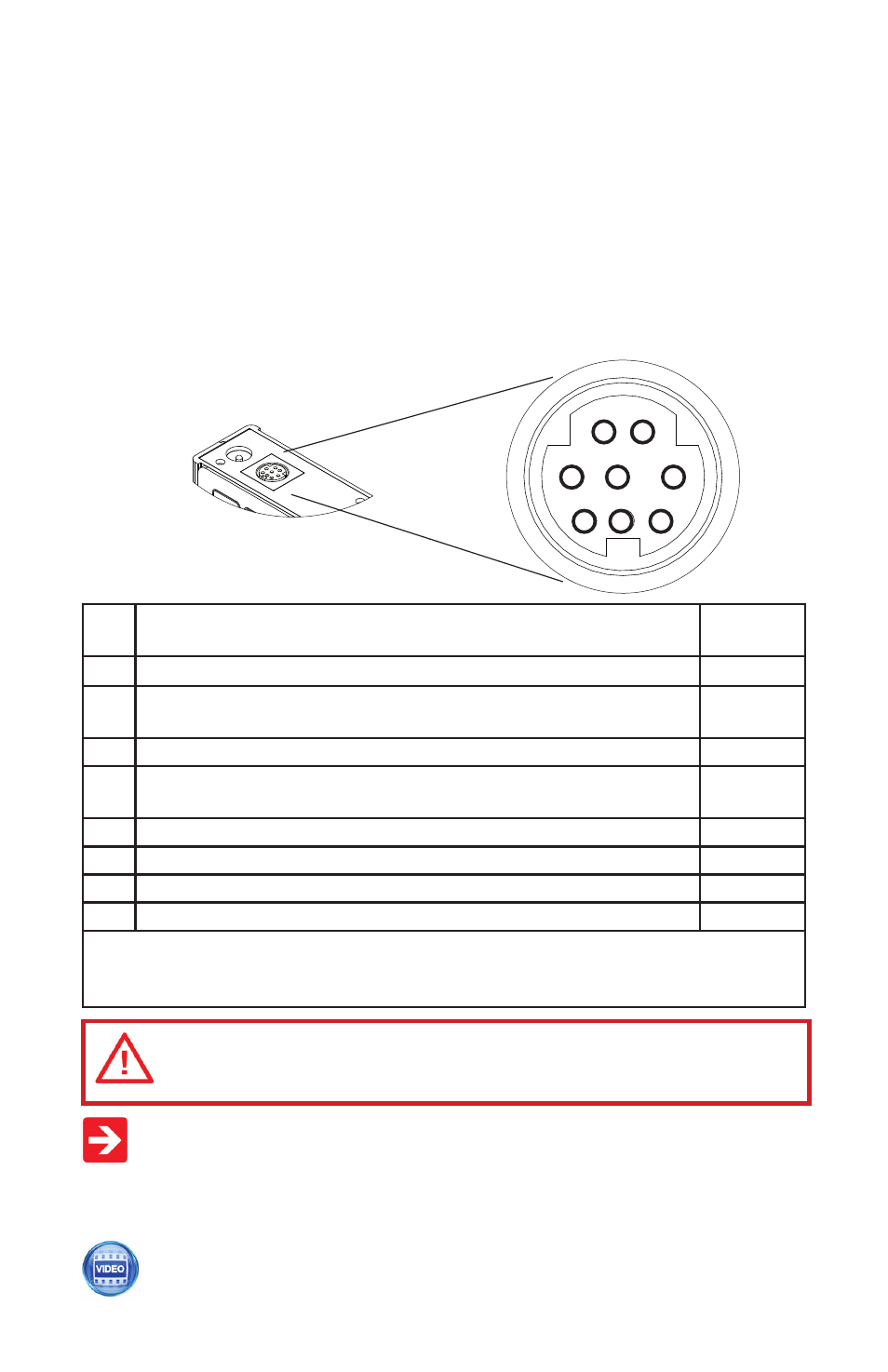
Standard 8 Pin Mini-DIN Pin-Out
1
2
3
4
5
6
7
8
Pin Functi on
Mini-DIN
cable color
1
Not Connected
(or opti onal 4-20mA Primary Output Signal)
Black
2
Stati c 5.12 Vdc [or opti onal Secondary Analog Output (4-20mA,
5Vdc, 10Vdc) or Basic Alarm]
Brown
3
Serial RS-232RX / RS-485(–) Input Signal (receive)
Red
4
Meters/Gauges = Remote Tare (Ground to Tare)
Controllers = Analog Set-Point Input
Orange
5
Serial RS-232TX / RS-485(+) Output Signal (send)
Yellow
6
0-5 Vdc (or opti onal 0-10 Vdc) Output Signal
Green
7
Power In (as described above)
Blue
8
Ground (common for power, communicati ons and analog signals)
Purple
Note: The above pin-out is applicable to all the fl ow meters and controllers with the
Mini-DIN connector. The availability of diff erent output signals depends on the opti ons
ordered. Opti onal confi gurati ons are noted on the unit’s calibrati on sheet.
CAUTION! D� ��� ������� ����� �� ���� 1 ������� 6 �� ���������
������ ��� �����!