Diagnostics – West Control Solutions CALogix User Manual
Page 13
4.
Click on ‘CALogix’ icon.
5.
CALogix program should now run.
USING CALOGIX-SW
1.
Refer to on-screen help or CALogix programming manual contained on CALogix-sw CD.
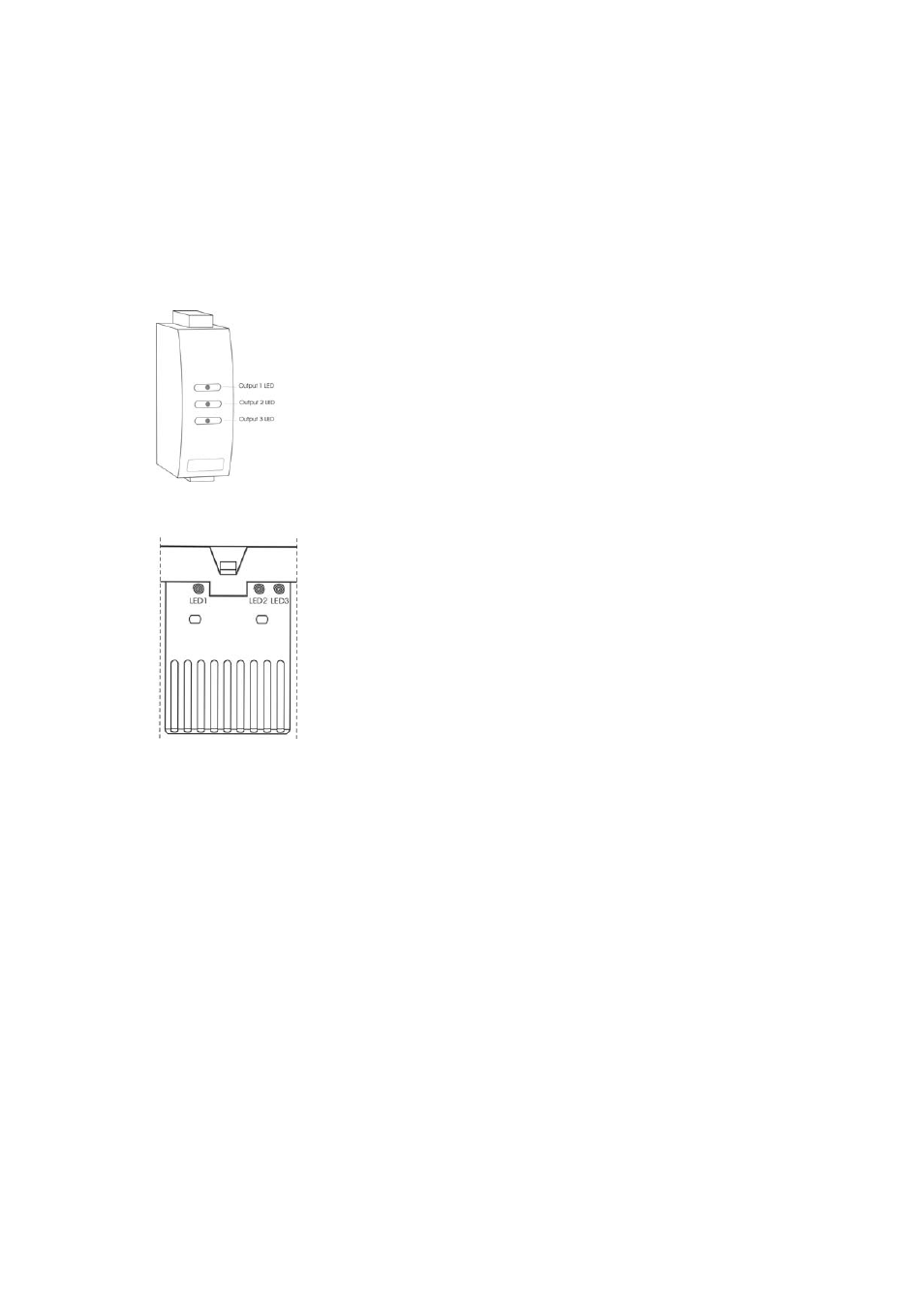
Diagnostics
Each control module has LEDs to indicate when each of the outputs are on (or relay closed). If an analogue output option
is fitted the LED dims proportionately with the output level, e.g. a PID module with a 4-20mA output, the LED will be dim at
4mA and bright at 20mA.
Note
: The output and the LED indicator are physically linked and always represent the true state of the output.
CALogix base-unit has three status LED’s to assist with diagnosing problems
LED 1 – Communications
Off
No
communications
On/Pulsing Communications
active
LED 2 – CALogix healthy (Heartbeat)
Slow pulse
Unit operating correctly
Fast Pulse
Base-unit emergency (comms still running)
On
Base-unit
lock-up
When base-unit emergency/lock-up conditions exist recycle power to clear. If the
problem does not clear on power recycle contact CAL controls for technical support.
LED 3 – Logic
Off
Logic not active
On
Logic
active
To start logic program running refer to section on running logic programs
Page 13 of 44