Wiring check, Criteria of judgment and cause – KYORITSU 6310 Quick Manual User Manual
Page 44
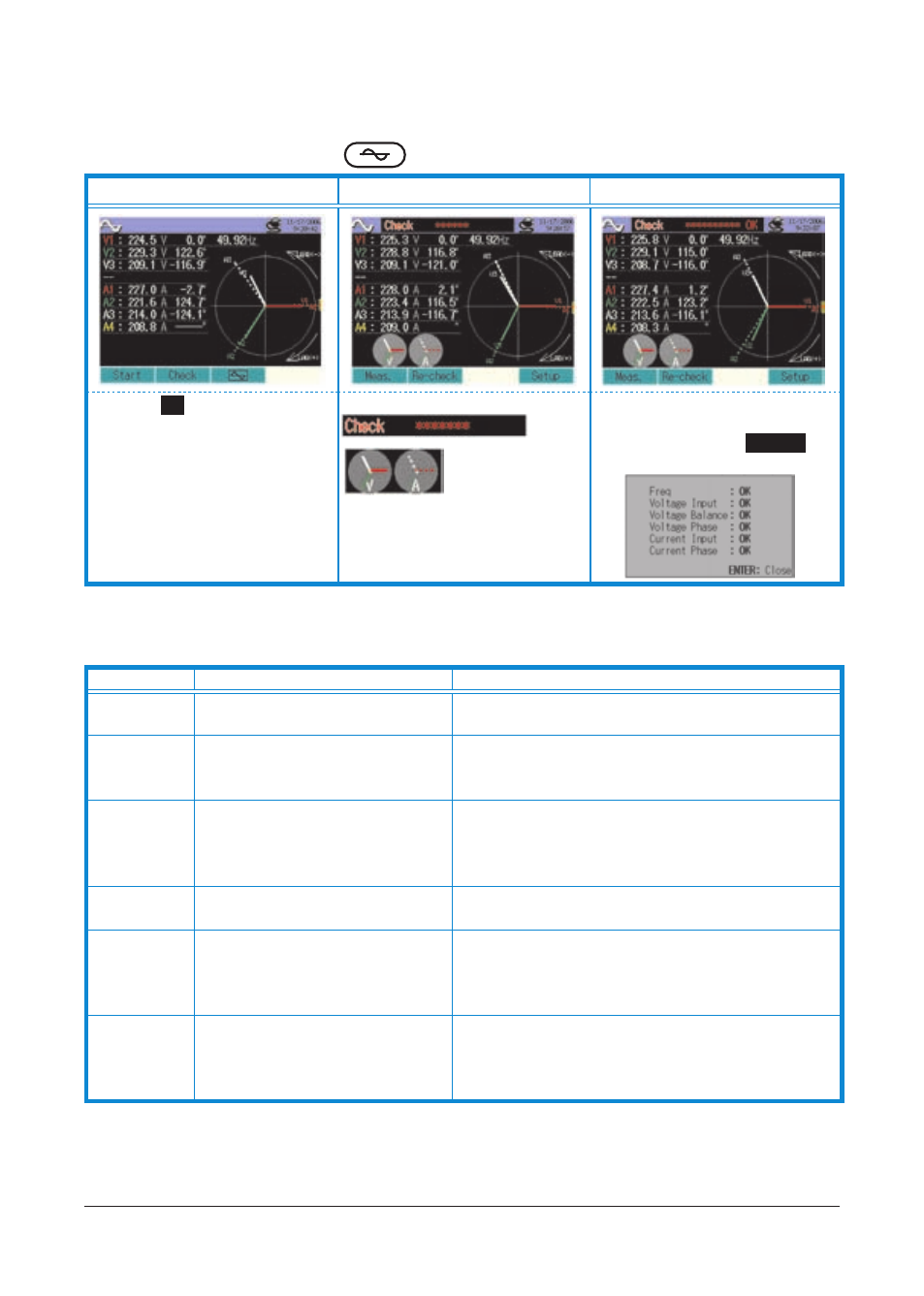
12. Wiring check
Proper wirings can be checked at
WAVE Range.
1. Ordinal screen
2. Checking wiring
3. Check completes
Press the
F2
Key.
Wiring check starts.
[Checking status] &
[Proper vector]
are displayed.
Wiring check completes.
In case of NG, Error message
appears. (Press the
ENTER
Key
when OK is displayed.)
* Check results may by affected if great power factors exist at the measurement sites.
Criteria of Judgment and cause
Check
Criteria of Judgment
Cause
Frequency
Frequency of V1 is between 42 and
68Hz.
• Voltage clip is firmly connected to the DUT?
• Measuring too high harmonic components?
Voltage input Voltage input is 10% or more of
(Voltage Range x VT).
• Voltage clip is firmly connected to the DUT?
• Voltage test leads are firmly connected to the
Voltage input terminals on the instrument?
Voltage
balance
Voltage input is within ±30º of
reference voltage (V1)
* (not judged by single-phase
wiring)
• Setting against the wiring under test are matched?
• Voltage clip is firmly connected to the DUT?
• Voltage test leads are firmly connected to the
Voltage input terminals on the instrument?
Voltage phase Phase of voltage input is within ±10º
of reference value (proper vector).
• Voltage test leads are properly connected?
(Connected to proper channels?)
Current input Current input is 5% or more of
(Current Range x CT).
• Clamp sensors are firmly connected to the Power
input terminals on the instrument?
• Setting for Current Range is appropriate for input
levels?
Current phase Current input is within ±60º of
reference value (proper vector).
• Arrow mark on a Clamp sensor and the orientation
of flowing current is matched? (Power supply to
Load)
• Clamp sensors are connected properly?
KEW6310
−
42 −