Transducer cable extensions for bm90 / l, Figure 4:transducer wiring for differential mode – KROHNE BM 90 EN User Manual
Page 8
8
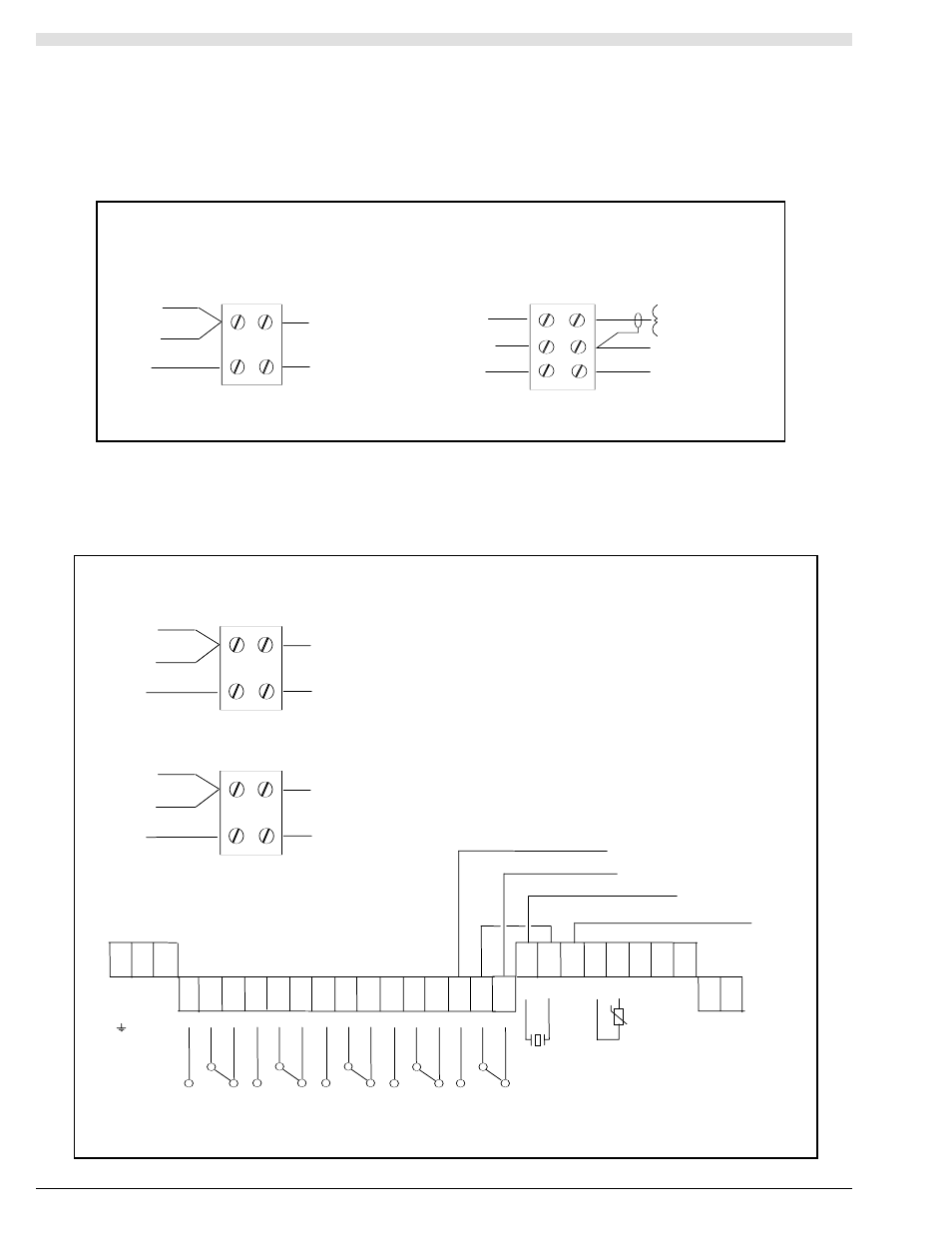
2.1.3. Transducer Cable Extensions for BM90 / L
Transducer cables may be extended using junction boxes as shown below in Figure 3:
Junction
Screen - Term 19
Standard Transducer
Transceiver
Core - Term 20
Transducer
Black
Screen
Blue
RG62AU
Temperature Compensation Transducer
RG62AU
Blue
Junction
Core
- Term.22
Screen
-
Term.19
Core - Term. 20
Screen
-
Term.19
Transceiver
Transducer
Black
Screen
Figure 4:Transducer Wiring for Differential Mode
UP & DOWNSTREAM SHIELD
Junction
Screen - Term 19
Transceiver
Core - Term 18
Upstream Transducer
Black
Screen
Blue
RG62AU
Junction
Screen - Term 21
Transceiver
Core - Term 16
Downstream Transducer
Black
Screen
Blue
RG62AU
Extend transducer cable if necessary
with RG62AU as shown.
1 2 3
E N L
L2 L1
AC POWER
110/230 VAC
+10%/-10%
50/60 HZ 12VA
4 5 6 7 8 9 10 11 12 13 14 15 16 17 18
RELAY 1
RELAY 3
RELAY 2
27 28
+ -
DC POWER
21.6-30VDC
9W
19 20 21 22 23 24 25 26
ISOLATED
ANALOG
OUTPUT
-
SH
IE
LD
HOT
.B
LU
E
BL
AC
K
+
TEMP
SENSOR
TRANS-
DUCER
SH
IE
LD
RELAY 4
RELAY 5
LINK
UPSTREAM - BLUE
DOWNSTREAM - BLUE
UP & DOWNSTREAM BLACK
- BATCHFLUX 5500 C Quickstart EN (20 pages)
- IFC 050 Converter Quickstart EN (28 pages)
- IFC 100 Converter Quickstart EN (32 pages)
- IFC 300 Converter Quickstart EN (68 pages)
- OPTIFLUX 1000 Quickstart EN (20 pages)
- OPTIFLUX 2000 Quickstart EN (24 pages)
- OPTIFLUX 4000 Quickstart EN (24 pages)
- OPTIFLUX 4040C Quickstart EN (16 pages)
- OPTIFLUX 5000 Flange Quickstart EN (20 pages)
- OPTIFLUX 5000 Sandwich Quickstart EN (20 pages)
- OPTIFLUX 6000 Quickstart EN (28 pages)
- OPTIFLUX 7300 Quickstart EN (24 pages)
- OPTIPROBE Quickstart EN (16 pages)
- TIDALFLUX 2300 F EN (44 pages)
- TIDALFLUX 2300 F Quickstart EN (24 pages)
- WATERFLUX 3000 EN (40 pages)
- WATERFLUX 3000 Quickstart EN (24 pages)
- WATERFLUX 3070 EN (80 pages)
- WATERFLUX 3070 Quickstart EN (32 pages)
- USB ADAPTER PLUS EMF EN (16 pages)
- IFC 050 Converter Modbus EN (20 pages)
- IFC 100 Converter FOUNDATION FIELDBUS EN (64 pages)
- IFC 100 Converter Modbus EN (20 pages)
- IFC 300 Converter FOUNDATION FIELDBUS EN (60 pages)
- IFC 300 Converter HART 0102 EN (20 pages)
- IFC 300 Converter HART 0201 EN (23 pages)
- IFC 300 Converter Modbus EN (24 pages)
- IFC 300 Converter PROFIBUS PA DP EN (40 pages)
- OPTIFLUX 2000-4000 IECEx EN (16 pages)
- OPTIFLUX 2000-4000-5000-6000-7300-IFC 300 Ex EN (40 pages)
- OPTIFLUX 2000-4000-5000-6000 -IFC 100 Ex EN (24 pages)
- OPTIFLUX 4040 C Ex EN (20 pages)
- OPTIFLUX x300 Ex Zone2 EN (1 page)
- H250 M9 ES EN (36 pages)
- VA 40-VA 45 EN (36 pages)
- H250 M10 ATEX II2G Ex d EN (16 pages)
- H250 M10 ATEX II3D Ex t EN (16 pages)
- H250 M40 ATEX II2D Ex t-II2G Ex d EN (20 pages)
- H250 M40 ATEX II2G Ex i EN (20 pages)
- H250 M40 ATEX II3G Ex nA EN (20 pages)
- H250 M40 Ex II2G Reed EN (2 pages)
- H250 M9 ATEX II2G Ex i EN (16 pages)
- H250 M9S ATEX II3D Ex t-II3G Ex nA EN (20 pages)
- M8E Converter HART 0101 EN (13 pages)
- DK 32-DK 34 ATEX II2G Ex i EN (16 pages)