Defining the connections for example 2, Defining the connections for example 2 -8, Figure 8-4. slot 0 module configuration menu -8 – ADTRAN ATLAS 810 Plus User Manual
Page 92: Defining the connections fo r example 2
Chapter 8. Dedicated Maps Terminal Menu
8-8
ATLAS 810
PLUS
User Manual
61200266L1-1
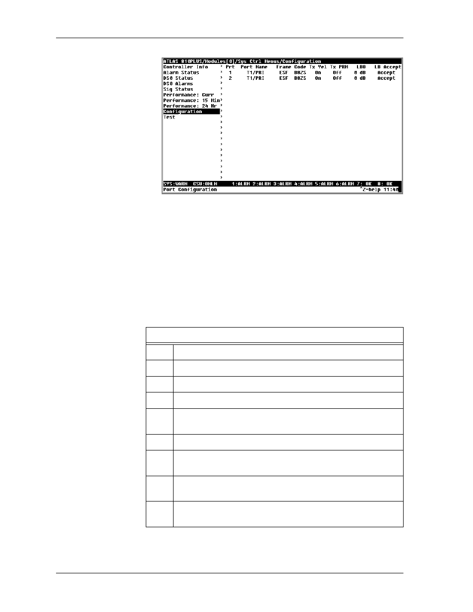
Figure 8-4. Slot 0 Module Configuration Menu
Defining the Connections for Example 2
Begin by navigating to
Dedicated Maps/Create/Edit Maps
and naming
your map. Navigate to
Dedicated Maps/Connects
. The
Connects
sub-
menu defines the connections necessary to route the required bandwidth.
Refer to Table 8-1 on page 8-7 to define each of the necessary connections.
For this procedure, first define the data connections, and then define the
voice connections. The following Step/Action tables guide you through this
process. (Figure 8-5 shows the completed map.)
Instructions for Defining Data Connections
Step
Action
1
For Data A, select and define FROM Slot
(
i.e.
,
0 Sys Ctrl
).
2
Select and define "from"
Port (i.e., port 1 for T1: Data A).
3
Select and define
From Config
DS0s (i.e.,
DS0=9-24).
4
Select and define
TO Slot
and “to”
Port
in the same way (i.e.,
2 V.35Nx4
and
1 where 2 = Slot 2 and 1 = Port 1.)
5
From To Config, set V.35 to operate at 56k/64k per DS0.
6
Repeat for the remaining data connections (i.e., Data B and
Data C) as follows:
6a
Insert new connection lines by positioning the cursor over the
index # of the first connection and pressing
I
.
6b
Copy the first connection by positioning the cursor on the index #
and pressing
C
.