Connection, Control/chain out port, Connection -5 – ADTRAN ATLAS 810 Plus User Manual
Page 33: Control/chain out port -5, Table 2-1, Control/chain in pinout -5
Chapter 2. Installation
61200266L1-1
ATLAS 810
PLUS
User Manual
2-5
Connection
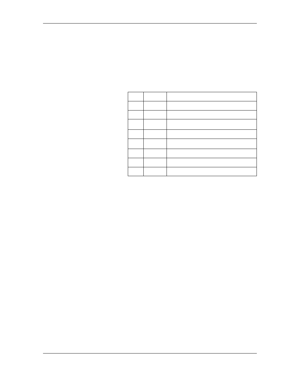
The Control/Chain In connection follows with the pinout shown in Table 2-1.
Control/Chain Out Port
The Control/Chain Out port (RJ-48C) connects to another ATLAS 810
PLUS
Chain In connector. The Control/Chain Out port output provides the fol-
lowing:
•
EIA-232 output to chain control to other ATLAS 810
PLUS
Base Units
•
2400, 9600, 19200, or 38400 bps operation
•
Automatic setup; no user input required
Connection
The Control/Chain Out connection follows, with the pinout shown in Table
2-2 on page 2-6.
Connector type
RJ-48C
Part number
AMP# 555164-2
Table 2-1. Control/Chain In Pinout
PIN
NAME
DESCRIPTION
1
GND
Ground - connected to unit chassis
2
RTS
Request to send - flow control
3
RXDATA
Data received by the ATLAS 810
PLUS
4
DTR
Data terminal ready
5
TXDATA
Data transmitted by the ATLAS 810
PLUS
6
CD
Carrier detect
7
UNUSED —
8
CTS
Clear to send - flow control
Connector type
RJ-48C
Part number
AMP# 555164-2