Using the local configurator – KROHNE VFM 3100 EN User Manual
Page 49
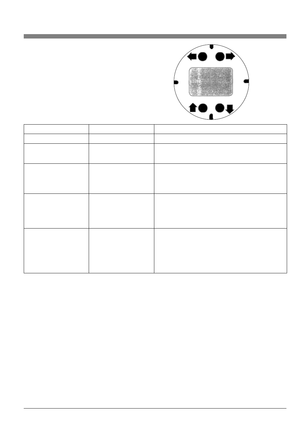
8.2.3. Moving inside the Menu System
Pressing ESC will stop displaying measurements, and show the first
menu item, DISPLAY. From here, the four buttons allow the user to
move around the menu tree, as indicated by the arrows. Press the
down arrow repeatedly; the menu display will cycle through each of
the top level (Level 1) menu items. Refer to the menu structure dia-
gram on the following pages as you move around
NOTE: Each menu item has its level (1 - 4) displayed at the beginning
of the top line.
The four buttons also allow the user to move up and down the pick-
lists, as indicated by the arrows. Also, pressing ESC moves one from
the current level to the next higher level. Pressing ESC within the top
level menu returns the user to the MEASURE block.
8. Local Configuration Instructions VFM 3100
8.1. Introduction
Local configuration of the VFM 3100 is accomplished via four multi-
function pushbuttons on the local keypad/display shown below.
A functional overview of the Menu Tree is presented in Table 12.
8.2. Using the Local Configurator
8.2.1. Measurements (MEASURE)
The system starts up displaying the measured Flowrate (FLOW), the
Total (TOTAL), or the Flow and Total (BOTH), in an alternating fashion,
depending on the selection made in the Calibrate/Show menu.
8.2.2. Display Bar Indicator
The analog bar indicator at the top of the display indicates the flow
measurement, as a percentage of the upper range value.
NOTE: If the flow measurement is out-of-range, the bar indicator will
blink. If the transmitter is off-line, the middle four bars of the bar indi-
cator will blink.
In TEST/SET DIG, the bar indicator continues to display the flow
measurement. However, in TEST/SET MA, it displays the per-
centage of span set.
49
Level 1
Level 2
Function
MEASURE
Display Flowrate and Total
DISPLAY
OPTIONS
Display Transmitter and Output Options
PARAMS
Display Fluid and Application Parameters
TAGS
Display Flowtube and ID Parameters
CALIB
SHOW
Set Measurement Display Mode
LFCI
Set Low Flow Cut-In
RESET TOTAL
Set Total to Zero
CAL 4 mA
mA Calibration @ 4 mA
CAL 20 mA
mA calibration @ 20 mA
TEST
DIAG
Display Status
SET DIG
Set Digital Output for Loop Calibration
SET MA
Set 4-20 mA Output for Loop Calibration
SET HZ
Set Scaled Pulse Output for Loop Calibration
SELFTST
Activate Transmitter Self-Test
XMTTEMP
Display Transmitter Temperature
CONFIG
OPTIONS
Select Transmitter Options
OUTPUT
Select Output Option
FLUID
Enter Fluid Parameters
UNITS
Enter Units, URV, and Damping
BIAS
Enter Application Parameter
TAGS
Enter Identification Parameters
NEWTUBE
Enter Flowtube Parameters
PASSWD
Change Passwords
Table 12. Menu Tree Functional Overview