KROHNE VFM 3100 EN User Manual
Page 20
20
Twisted pair wiring should be used to prevent electrical noise from
interfering with the dc current output signal. In some instances,
shielded cable may be necessary. Earthing (grounding) of the shield
should be installed at one point only (at the power supply). Do not
earth (ground) the shield at the transmitter.
Transmitter connection polarities are indicated on the terminal block.
If the loop is to contain additional instruments, install them between
the negative terminal of the transmitter and the positive terminal
of the receiver, as shown in Figure 11.
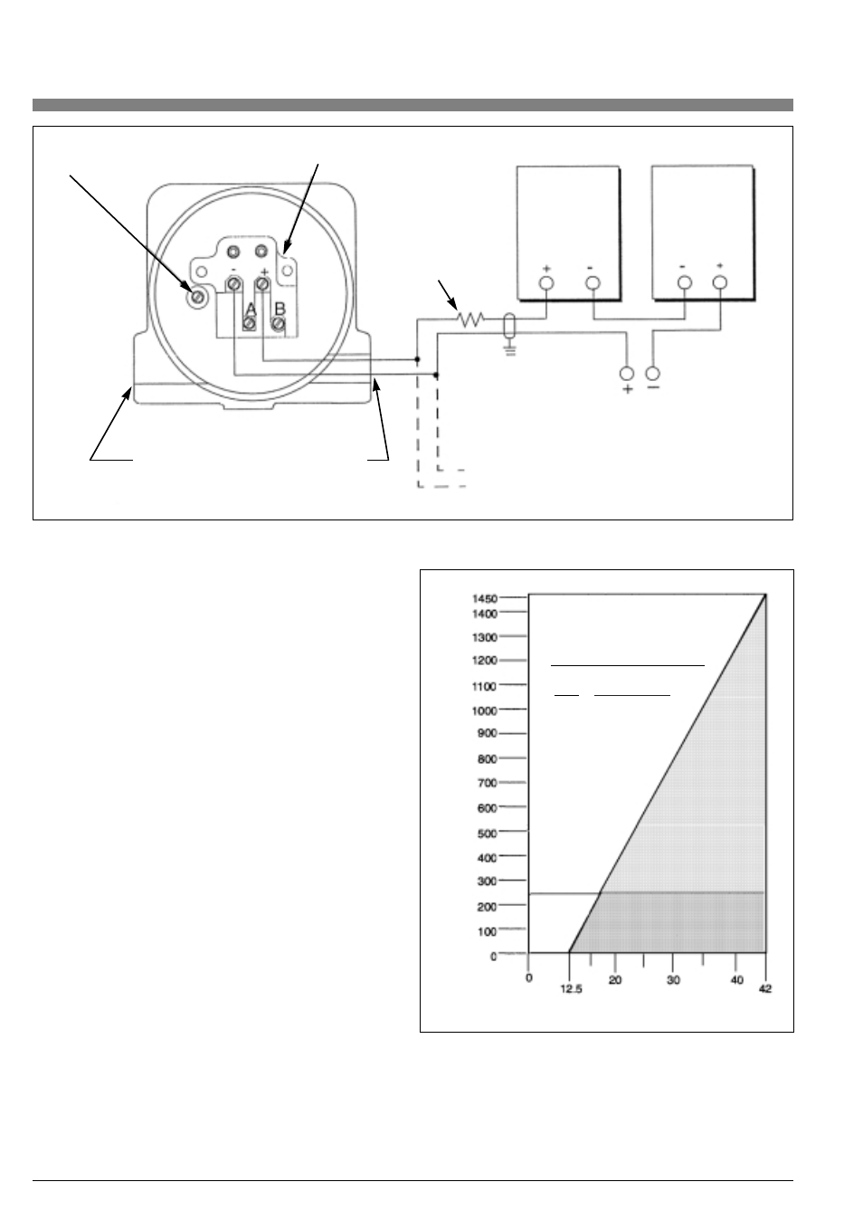
Power Supply and External Load
The required loop power supply voltage is based on the total loop
resistance. To determine the total loop resistance, add the series
resistance of each component in the loop (do not include transmit-
ter). The required power supply voltage can be determined from
Figure 12.
The transmitter will function with an output load less than 250 ohms,
provided that a configurator is not connected to it. Connecting a
configurator to a loop with less than 250 ohms may cause communi-
cation problems.
As an example, for a transmitter with a loop resistance of 500 ohms,
referring to Figure 12, the minimum power supply voltage is 22 V dc,
while the maximum power supply voltage is 42 V dc. Conversely,
given a power supply voltage of 24 V dc, the allowable loop resi-
stance is from 200 to 565 ohms.
NOTES:
• The power supply must be capable of supplying 22 mA.
•
Power supply ripple must not allow the instantaneous voltage
to drop below 12.5 V dc at the transmitter.
•
The recommended minimum load is 250 ohms.
Case ground
terminal (earth)
Power
supply
Receiver
Additional
receivers
in loop.
250 ohm min load
required for
communication
Hart communicator.
Connect to loop to configure transmitter.
Two 1/2 NPT conduit connections are provided
(on opposite sides). Insert plug in connection
not used.
Terminal block
Figure 11. Installation Wiring -4-20 mA Output (Two-wire)
Figure 12. Load Requirements
Recommended supply voltage
and load limits
VDC
24
30
32
Load (OHMS)
250 and 565
250 and 860
250 and 960
Operating area
See note below
Supply voltage, V dc
Output load,
ȑ
Min.
Load