KROHNE VFM 3100 EN User Manual
Page 42
4.7.2. Assembly
NOTE: Before beginning the assembly procedure, verify that you ha-
ve the correct kit of parts.
The sensor kits consist of:
1 Sensor Assembly
1 O-ring
1 Gasket
1 Flow Dam
Slide O-ring over sensor lead and onto neck of sensor.
See Figure 29.
The following steps apply to both Standard and Extended Tempera-
ture Range VFM 3100:
•
If the flow dam has remained in the VFM 3100 body, remove it
before starting to reassemble.
•
Carefully feed sensor lead through hole in mechanical connector
and gently pull sensor lead out of junction box until sensor is
touching the mechanical connector. See Figure 37.
CAUTION: For CENELEC certified flameproof units, take special
care not to scar, mar, ding, or dent the surface of the sensor stem
during assembly. This is critical to the integrity of the flameproof sur-
face finish.
•
Place the flat gasket over the sensor in contact with the serrated
sealing surface. Center the gasket. Slide the flow dam into the
groove on the sensor.
•
Insert the sensor with the connector into the VFM 3100 body
and assemble the four bolts finger tight.
WARNING: It is important that the gasket be sealed uniformly to
provide a good seal. The following steps will assure a uniform seal.
Failure to follow these steps could result in personal injury due to
gasket leakage.
•
Tighten all connector bolts to 3.4 Nm (25 lb•ft) per the
procedure starting on page 40. Refer to Figures 32 and 33.
•
Attach conduit connections and input wiring. See “Field
Termination” on page 19.
NOTE: Replacing the sensor will not cause a shift in the K-factor.
Therefore, the VFM 3100 does not require recalibration.
•
Connect the sensor wires to the color coded terminals as shown
in Figure 34 for the Standard Temperature Range sensor and in
Figure 35 for the Extended Temperature Range sensor.
WARNING: In order to maintain agency certification of this product
and prove integrity of the parts and workmanship in containing pro-
cess pressure, a hydrostatic pressure test must be performed. The
VFM 3100 must hold for 1 minute without leaking the appropriate
pressure from Table 11, “Maximum Test Pressure,” on page 40.
42
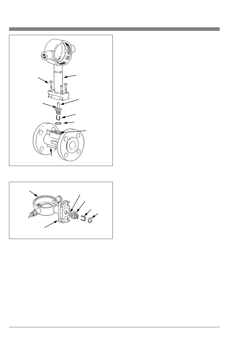
Mechanical
connector
bolts (4)
Mechanical
connector
Sensor
assembly
Flow dam
Gasket
Sensor
assembly
O-Ring
Flow dam
Gasket
Access hole
Body
O-Ring
Junction box
Mechanical connector
Figure 36. VFM 3100 Assembly/Junction Box
Figure 37. Sensor/Mechanical Connector/Junction Box