KROHNE VFM 3100 EN User Manual
Page 21
A dc power supply must be used with each transmitter and receiver
wiring loop to supply power for the transmitter. The dc power supply
may be either a separate signal unit, a multiple unit supplying power
to several transmitters, or built into the receiver.
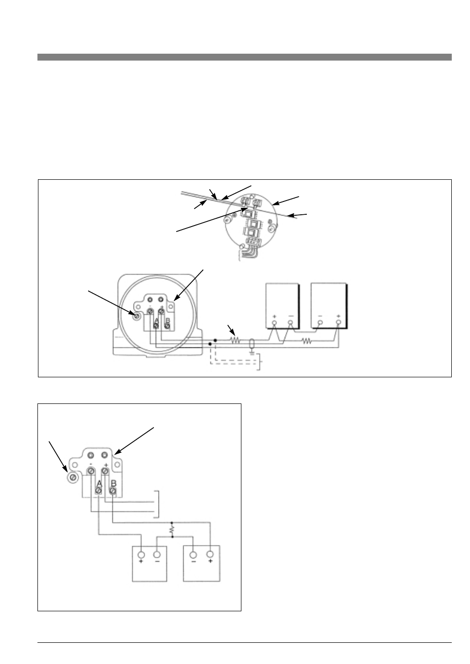
Connect the supply and receiver loop wiring for pulse out (0.50 mm
2 or 20 AWG typical) to the terminals in the field-terminal compart-
ment of the transmitter, as shown in Figure 13. To use this type of
3-wire hookup, the blue and green terminals on the back of the
module must be shorted.
A resistor is required to produce a voltage drop for proper operation
of the counter. A 680 ... 2 W resistor is recommended for most coun-
ters.The pulse signal can cause interference to signals in adjacent
signal cables. In some instances, shielded cable may be necessary.
Earth grounding of the shield should be at one point only (at the po-
wer supply). Do not ground the shield at the transmitter. Transmitter
connection polarities are indicated on the terminal block.
Power Supply and Load
The power supply voltage must be between 12.5 and 42 V dc. The
pulse "OFF" state current is a maximum of 0.42 mA at 42 V dc. In the
"ON" state, the pulse output is short circuit protected for 250 mA.
Four-Wire Hook-up
Two separate loops are required when using the scaled pulse output
in the four-wire hook-up arrangement. Each loop requires its own
power supply. Refer to Figure 14.
Select the resistor so that the current through the contact closure
does not exceed 250 mA.
Wiring may be run in conduit or in wireways. The wiring must meet all
applicable local standards such as hazardous location requirements
and electrical wiring codes. Signal wires should not be run in the
same conduit as power wires. Shielded twisted pair wiring is recom-
mended.
21
Three-Wire Hook-up (See Figure 13)
Scaled Pulse Output
This wiring is primarily used to retrofit VFM3100 transmitters that
were wired as pulse only transmitters for totalization. This wiring is
typically for retrofitting existing installations. Configure the transmitter
for pulse output. Refer to the section on changing the configuration
beginning on page 23.
For new installations, a four-wire hook-up is recommended
for scaled pulse operation to improve communication inte-
grity.
Red (+)
Output signal wires
Back of module
electronics side
Yellow (P)
Terminal block
Case ground
terminal
(earth)
250 OHM min.
load required for
communication
Hart communicator. Connect to loop
to configure transmitter.
Power
supply
Counter
680 OHM
Blue (-)
Shorting wire across
B and G
Sensor/preamplifier wires
Figure 13. Installation Wiring – Pulse Output (Three-wire)
Case ground
terminal (earth)
Terminal block
4-20 mA loop
680
Ω
Power
supply
Counter
Scaled pulse loop
Figure 14. Installation Wiring (Four-wire)