Sensor replacement with remote electronic module – KROHNE VFM 3100 EN User Manual
Page 41
41
4.7. Sensor Replacement with Remote
Electronic Module
4.7.1. Disassembly
•
Remove junction box cover (for CENELEC Certified Flameproof
VFM 3100, remove lock assembly and cover). See Figure 24.
a.
Standard Temperature Range Sensor: Loosen strain relief
clamp. Disconnect yellow and brown sensor leads from
terminal block. See Figure 34.
b.
Extended Temperature Range Sensor: Disconnect brown
and yellow sensor lead from terminal block on preamplifier.
See Figure 35. (For CENELEC Certified Flameproof
VFM 3100, remove preamplifier shield and then disconnect
the sensor leads from preamplifier.)
Remote cable
Brown (+)
Red
Orange
Yellow (-)
Ground (earth) screw
(cenelec flameproof only)
Sensor wires
Sensor switch
Preamplifier assembly
•
Do not disconnect the interconnecting wiring to the remote
Electronic Module assembly.
•
See Figure 36. Remove mechanical connector bolts.
(CENELEC Certified Flameproof VFM 3100 have special
connector bolts as well as a shroud plate over the standard
connector. Once the bolts are removed, the shroud plate is
retained between the connector and housing.)
•
Lift the junction box mechanical connector and sensor as a unit.
•
Slide the sensor and out of the mechanical connector as shown
in Figure 37.
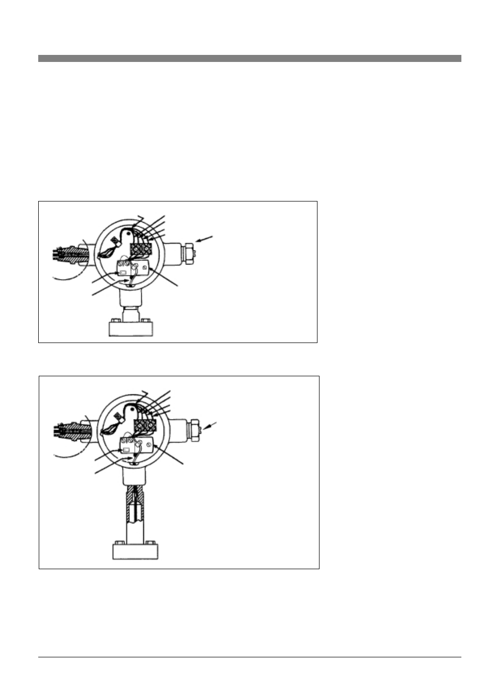
Figure 34: Flowtube/Junction Box - Standard Temperature Range
Figure 35: Flowtube/ Junction Box - Extended Temperature Range
Remote cable
Brown (+)
Red
Orange
Yellow (-)
Ground (earth) screw
(cenelec flameproof only)
Sensor wires
Sensor switch
Preamplifier assembly