2 turning the power supply on, Figure 3-1. lcd power on defaults, Turning the power supply on -4 – KEPCO ABC-DM SERIES User Manual
Page 36: Lcd power on defaults -4
3-4
ABC 040104
3.3.2
TURNING THE POWER SUPPLY ON
When the power supply is turned on, it performs a self-test and displays the status in the LCD.
After completing the self-test the LCD first shows the power supply type, e.g., Kepco
ABC10-
10 GPIB addr. = nn
, where nn is the GPIB address (factory default GPIB address = 6).The
LCD then shows the power on defaults (see Figure 3-1). The defaults are: output enabled, volt-
age mode, output voltage set to zero, output current set to a minimum value (1-2% of I
O
max).
Power on defaults also include setting maximum values for overcurrent and overvoltage protec-
tion indicated in Table 1-2.
NOTE: The power supply can be programmed to power up with output set to OFF. See PAR.
3.3.6.1.
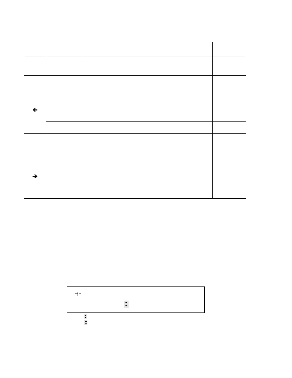
FIGURE 3-1. LCD POWER ON DEFAULTS
2
Data Entry
Press to enter number 2.
3
Data Entry
Press to enter number 3.
ENTER
Data Entry
Press to accept data entered and return to Command Entry status.
Command Entry
— In CV (constant voltage), press to decrease output voltage by increment
equal to voltage resolution (
≤
.0.025% of EOmax).
— In CC (constant current), press to decrease output current by increment
equal to current resolution (
≤
.0.025% of IOmax).
— In EDIT PROG status, changes the parameter displayed on LCD for a
specific memory location and decrements memory location displayed on
LCD.
Data Entry
Erases number to left, or decreases value shown (e.g. Display Contrast set-
ting).
0
Data Entry
Press to enter number 0.
( . )
Data Entry
Press to enter decimal point
Command Entry
— In CV (constant voltage), press to increase output voltage by increment
equal to voltage resolution (
≤
.0.025% of EOmax).
— In CC (constant current), press to increase output current by increment
equal to current resolution (
≤
.0.025% of IOmax).
— In EDIT PROG status, changes the parameter displayed on LCD for a
specific memory location and increments memory location displayed on
LCD
Data Entry
Not used.
—
TABLE 3-1. KEY FUNCTIONS (CONTINUED)
KEY
POWER SUPPLY
STATUS ACTIVE
DESCRIPTION
REFERENCE
PARAGRAPH
Loc
CV
0.000A
0.000V
NOTE:
indicates blinking colon (:), Command Entry status
indicates blinking equal sign (=), Data Entry status