HT instruments MACROTEST G3 User Manual
Page 65
MACROTESTG3 - COMBIG3
EN - 64
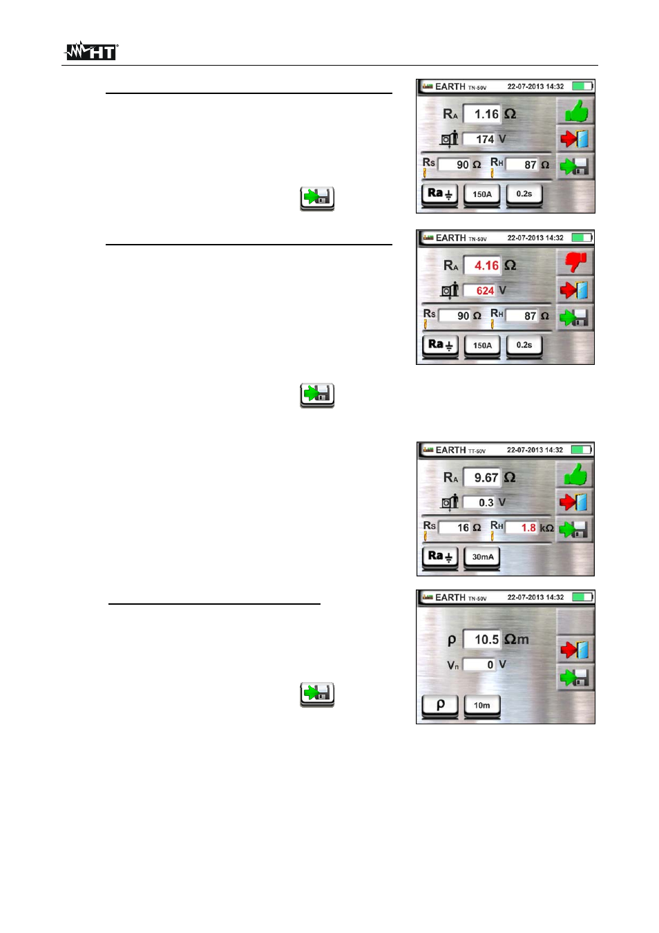
16 For earth resistance measurement in TN systems, in
case of positive result (see § 12.11), the screen to the
side is displayed by the instrument. It contains the
value of contact voltage in the secondary display, the
value of contact resistance of the voltage probe (Rs)
and the value of contact resistance of the current probe
(Rh).
Press the SAVE button or touch the
icon to save
the measurement (see § 7.1).
17 For earth resistance measurement in TN systems, in
case of negative result (see § 12.11), the screen to the
side is displayed by the instrument. It contains the
value of contact voltage in the secondary display, the
value of contact resistance of the voltage probe (Rs)
and the value of contact resistance of the current probe
(Rh).
Note the presence of the measurement result
highlighted in red.
Press the SAVE button or touch the
icon to save
the measurement (see § 7.1).
18 If the resistance value of Rs or Rh probes is > 100 *
Rmeasured the instrument performs the measurement
considering an accuracy of 10% of reading and marks
the value in red in corrispondance of Rs and/or Rh the
screen to the side is displayed
19 For ground resistivity measurement, the screen to
the side is shown by the instrument. It contains the
value of "
" expressed in m and the "Vn" value of the
possible interfering voltage measured by the instrument
during the test.
Press the SAVE button or touch the
icon to save
the measurement (see § 7.1).