HT instruments MACROTEST G3 User Manual
Page 24
MACROTESTG3 - COMBIG3
EN - 23
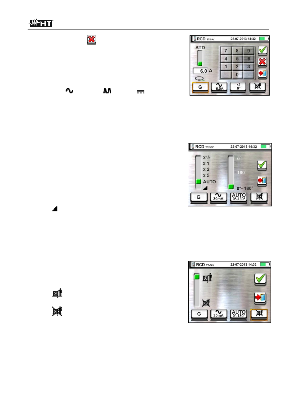
5.
Touch the icon
to zero the value in “A” field
and use the virtual keyboard to set the value of
rated current of earth leakage relay RCD. The
maximum rated current is 10.0A. Confirm the
choice by going back to the previous screen.
Move the second slide bar reference by selecting
the waveform of the differential switch between the
options:
(type AC),
(type A),
(type B).
For RCD of molded case type STD move the third
slide bar reference by selecting the desired rated
current of the differential switch between the
options: 10, 30, 100, 300, 500, 650, 1000mA
Confirm the choice by going back to the initial
measurement screen. Note the presence of the
chosen selections
6. Touch the third icon at the bottom of display and
select the desired type of test among the following
options:
x ½ Manual with multiplier ½ Idn
x 1 Manual with multiplier 1Idn
x 2 Manual with multiplier 2Idn
x 5 Manual with multiplier 5Idn
AUTO Automatic mode (6 tests in
sequence)
Ramp (measurement of the real tripping
current)
Move the right slide bar reference by selecting the
polarity of the test current between the options: 0°
(direct polarity), 180° (inverted polarity), 0°-180°
(for Automatic mode only). Confirm the choice by
going back to the initial measurement screen. Note
the presence of the chosen selections
7. Touch the fourth icon at the bottom of the display
and select the possible visualization of the contact
voltage value at the end of measurement. The
following options are possible:
The value of contact voltage is shown
on the display at the end of measurement
The value of contact voltage is not
shown on the display at the end of
measurement. The symbol “- - -“ is shown by
the instrument in this condition
8. Insert the green, blue and black connectors of the three-pin shuko plug into the
relevant instrument input terminals B3, B4, B1. As an alternative, use the single cables
and apply the relevant alligator clips to the free ends of the cables. It is also possible to
use the remote lead by inserting its multipolar connector into the input lead B1.
Connect the shuko plug, the alligator clips or the remote lead to the electrical mains
according to Fig. 10, Fig. 11, Fig. 12, Fig. 13 and Fig. 14.