Caution – HT instruments MACROTEST G3 User Manual
Page 32
MACROTESTG3 - COMBIG3
EN - 31
6.4.
LOOP:
LINE IMPEDANCE/LOOP AND OVERALL EARTH RESISTANCE
This function is performed in compliance with standard IEC/EN61557-3 and allows
measuring the line impedance, the fault loop impedance and the prospective short-circuit
current.
CAUTION
Depending on the selected electrical system (TT, TN or IT) some kind of
connection and function modes are disabled by the instruments (see Table 2 )
The following operating modes are available
L-N Standard (STD) measurement of the line impedance between the phase
conductor and the neutral conductor and calculation of the assumed phase-to-
neutral short-circuit current. This measurement is carried out even with high
resolution (0.1m
) through the optional accessory IMP57.
L-L
Standard (STD) measurement of the line impedance between the two phase
conductors and calculation of the assumed phase-to-phase short-circuit current.
This measurement is carried out even with high resolution (0.1m
) through the
optional accessory IMP57.
L-PE Standard (STD) measurement of the fault loop impedance between the phase
conductor and the earth conductor and calculation of the assumed phase-to-
earth short-circuit current. This measurement is carried out even with high
resolution (0.1m
) through the optional accessory IMP57.
Ra Global earth resistance without causing the differential protections tripping in
systems with and without neutral (see § 12.11).
CAUTION
The measurement of line impedance or fault loop impedance involves the
circulation of a maximum current according to the technical specifications of
the instrument (see § 10.1). This could cause the tripping of possible
magnetothermal or differential protections at lower tripping currents.
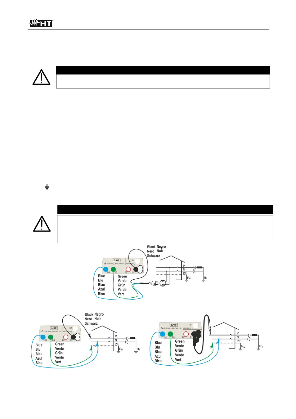
Fig. 16: P-N/P-PE measure for single-phase/two-phase 230V systems with shuko plug
Fig. 17: P-N/P-PE measure for single-phase/two-phase 230V systems with cables and
remote lead