GW Instek PST series Programming Manual User Manual
Page 4
PST & PSS & PSH SERIES PROGRAMMABLE POWER SUPPLY
PROGRAMMER MANUAL
⎯ 5 ⎯
z
Do not use more than 15m of cable to connect devices to a PC.
z
Ensure the same baud rate is used on the device as the one used on
PC terminal.
z
Ensure the connector for the both side of cable and the internal
connected line are met the demand of the instrument.
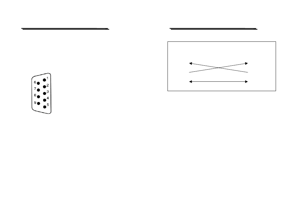
1.
No connection
2.
Receive Data (RxD)
(input)
3.
Transmit Data (TxD) (output)
4.
No connection
5.
Signal Ground (GND)
6.
No connection
7.
No connection
8.
No connection
9.
No connection
Figure 1 Pin assignments of the RS232 connector on the rear panel for DB-9-D
PST & PSS & PSH SERIES PROGRAMMABLE POWER SUPPLY
PROGRAMMER MANUAL
⎯ 6 ⎯
Figure 2 Wiring configuration for DB9 to DB9
Computer’s Connection
A personal computer with a COM port is the essential facilities in order
to operate the programmable power supply via RS232 interface.
The connections between power supply and computer are as follows:
I.
Connect one end of a RS232 cable to the computer.
II.
Connect the other end of the cable to the RS232 port on the
programmable power supply.
III.
Turn on the programmable power supply.
IV.
Turn on the computer.
EQUIPMENT
(DB9, DTE)
COMPUTER
(DB9, DTE)
Pin2
Pin3
Pin5
Pin5
Pin3
Pin2