Logic circuit test, Impedance matching network test – GW Instek SFG-2000 Series User Manual
Page 24
APPLICATION
EXAMPLES
47
Test step
1. Apply a triangle waveform to the amplifier first.
Adjust the waveform amplitude to make sure there is
no clipping.
2. Switch to square waveform and adjust its frequency
to the middle of the amplifier pass band, such as
20Hz, 1kHz, and 10kHz.
3. Observe the shape of the amplifier output. The
following table shows the possible output distortions
and their explanations.
•
Amplitude reduction at low
frequency
•
No phase shift
Transient
characteristic
list
•
Low frequency boosted (accentuated
fundamental)
•
High frequency loss
•
No phase shift
•
Low frequency phase shift
•
Trace thickened by hum-voltage
•
High frequency loss
•
Phase shift
•
Low frequency loss
•
Phase shift
•
Low frequency loss
•
Low frequency phase shift
•
High frequency loss
•
Low frequency phase shift
•
Damped oscillation
Note
For narrow band amplifier testing, square wave may not
be suitable.
SFG-2000 Series User Manual
48
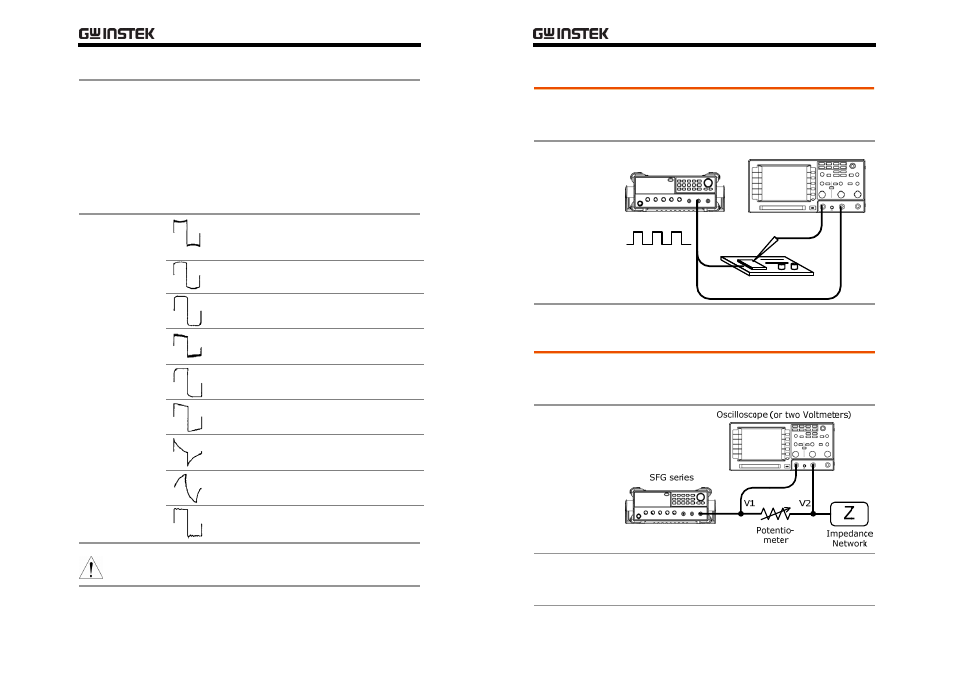
Logic Circuit Test
Description
Use the TTL/CMOS output from SFG-2000 series to
test digital circuits. Observe the timing relation of
input/output waveform using an oscilloscope.
Block diagram
SFG series
Oscilloscope
Digital Circuit
TTL/CMOS Out
Impedance Matching Network Test
Description
Use SFG-2000 series for impedance matching network:
testing its frequency characteristic and matching the
impedance.
Block diagram
Test step
Adjust the potentiometer until V2 becomes the half of
V1 (V2=0.5V1). Then the impedance Z of the network
becomes identical to the potentiometer.