GW Instek GOS-6100 Series User Manual
Page 24
GOS-6112 OSCILLOSCOPE
USER MANUAL
41
Comparing Frequency and phase (Single X-Y Operation)
To compare the frequency and phase between two signals by using the
X-Y mode. The X-Y waveform displays different amplitude, frequency,
and phase. The figure 5-7 shows a typical waveform made up of two
signals that are of the same frequency and amplitude, but approximate
45
o
out of phase.
To use the oscilloscope in the signal of X-Y mode, proceed the following
steps:
1. Connect the horizontal or X-axis signal to the CH1 input.
2. Connect the vertical or Y-axis signal to the CH2 input.
3. Set the CH1 off, and set the CH2 on.
4. Set the X-Y mode on by pressing and holding the button.
5. Set the TRIG SORCE button to CH1.
Use the HORIZONTAL POSITION control to adjust the X-axis.
Note: When high frequency signals are displayed in the X-Y
operation, note the frequency bandwidths and phase difference
between X and Y axis. Refer to “2. SPECIFICATION” section for
details.
Figure 5-7 Typical single X-Y display.
GOS-6112 OSCILLOSCOPE
USER MANUAL
42
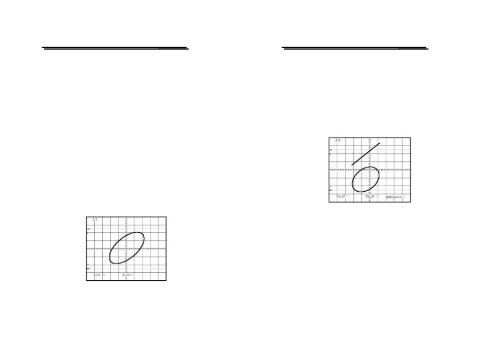
Setting up Dual X-Y Operation
To use the oscilloscope in the dual X-Y mode, proceed the following steps:
1. Connect the horizontal or X-axis signal to the EXT (X) input.
2. Connect one of the vertical or Y-axis signal to the CH1 (Y1) input.
3. Connect either of the vertical or Y-axis signal to the CH2 (Y2) input.
4. Set the CH1 and CH2 on.
5. Set the ALT/CHOP/ADD button to CHOP mode.
6. Set the X-Y mode on by pressing and holding the button.
The figure 5-8 shows two X-Y waveforms in the dual X-Y mode.
Figure 5-8 Typical dual X-Y display
Setting Up delayed-sweep Operation
A delayed sweep is used to magnify any portion of a complex waveform
in the horizontal direction.
To display the delayed sweep operation, proceed the following steps:
1. Briefly pressing the MAIN/ALT/DELAY pushbutton to set to MAIN
time base of the horizontal mode. Effect triggering by main sweep and
set MAIN TIME/DIV control as desired.