GW Instek GOS-6100 Series User Manual
Page 17
GOS-6112 OSCILLOSCOPE
USER MANUAL
27
Measurement and Panel setting Control
The measurement section controls the on-screen readout and the cursor
measurements.
33
FUNCTION
CURSOR
ON/OFF
(33)CURSOR FUNCTION-ON/OFF—Pushbutton with two functions.
ON/OFF
Pressing and holding either pushbutton to switch both cursor lines on
or off. As the cursor lines are part of the readout, they are visible only
when the readout is switched on.
CURSOR FUNCTION
Each time when the pushbutton is briefly pressed the seven
measurement functions will be selected in the sequence as below:
△V
:
Voltage difference measurement.
△V%
:
Voltage difference percentage measurement
(5div=100%
reference)
△VdB
:
Voltage gain measurement.
(5div=odB reference, △VdB=20 log, div/5div).
△T
:
Time difference measurement.
1/△T : Frequency
measurement.
△T%
:
Time difference percentage measurement.
(5div=100% reference).
△θ : Phase
measurement.
(5div=350
o
reference).
GOS-6112 OSCILLOSCOPE
USER MANUAL
28
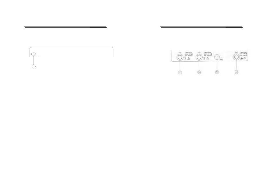
Input connectors
The input section is where the input signals are commonly connected to
the oscilloscope.
(35)CH1—Input BNC socket
This BNC socket is the signal input for channel 1. In X-Y mode,
signals at this input are used for the Y or X deflection. The outer
(ground) connection is galvanically connected to the instrument
ground and consequently to the safety earth contact of the line/mains
plug.
(36)CH2—Input BNC socket
This BNC socket is the signal input for channel 2. In X-Y mode,
signals at this input are used for the X or Y deflection. The outer
(ground) connection is galvanically connected to the instrument
ground and consequently to the safety earth contact of the line/mains
plug.
(37)Ground socket—Banana Socket galvanically connected to safety
earth.
This socket can be used a reference potential connection for DC and
low frequency signal measurement purposes.