Trigger controls – GW Instek GOS-6100 Series User Manual
Page 14
GOS-6112 OSCILLOSCOPE
USER MANUAL
21
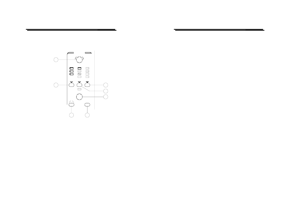
Trigger controls
The trigger controls determine the sweep start timing for both signal and
dual trace operation.
32
31
TRIGGER
LEVEL
SOURCE
DELAY TIME
26
SLOPE
27
TV
ATO
NML
MODE
-
TV-V/
TV-H
HO
30
29
28
COUPLING
DC
AC
LFR
HFR
CH2
CH1
EXT
+
(26)MODE – Pushbutton and indicator LEDs.
Pressing the pushbutton to select the trigger mode. The actual setting
is indicated by a LED.
Each time when the MODE pushbutton is pressed the trigger mode
changes in the sequence:
ATO—NML—TV—ATO
ATO (Auto)
Select the automatical mode, the sweep free-runs will display a
baseline trace when there is no trigger signal or the frequency is below
10Hz. The setting of triggering level changed only when the TRIGGER
LEVEL control is adjusted to a new level setting.
GOS-6112 OSCILLOSCOPE
USER MANUAL
22
NML (Normal)
Select the normal mode, the input signal will trigger the sweep when
the TRIGGER LEVEL control is set within the peak-to-peak limits of
an adequate trigger signal. When the sweep is not triggered, no
baseline trace will be displayed.
TV
Separate the video sync signal from the composite waveform and
direct it to the triggering circuit. The horizontal or vertical sync signals
are selected by TV-V/TV-H pushbutton. Please refer to the
TV-V/TV-H (31).
(27)LEVEL—Control knob
Turning the control knob causes a different trigger input setting
(voltage), and set to a suitable position for the starting of triggered
sweep of the waveform. An approximate trigger level setting (voltage)
value will be displayed in the readout. When rotate clockwise the
control knob, the trigger point moves toward the positive peak of the
trigger signal and rotate it counterclockwise to move the trigger point
toward the negative peak of the trigger signal.
When the setting (voltage) value is out of the changing portion of the
observation waveform, the synchronization sweep stops. Sometimes a
“?” will be displayed on the left of the valued display, that indicates
that direct reading is impossible if AC, HFR, LFR coupling or VAR of
vertical deflection is set.