GW Instek GOS-6103C User Manual
Page 8
GOS-6103C OSCILLOSCOPE
USER MANUAL
11
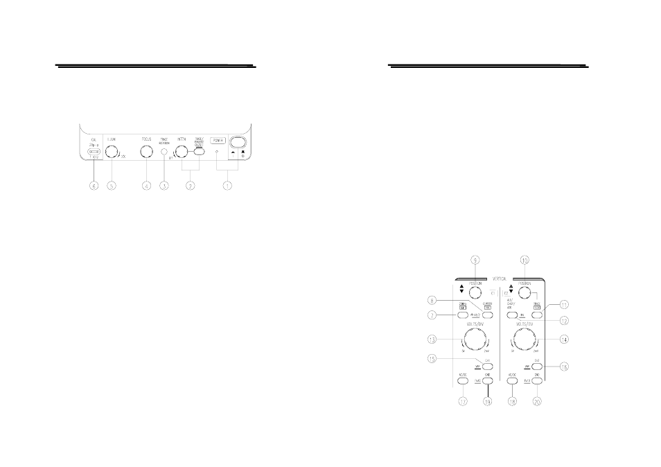
4-1.Front Panel
Display controls
The display controls adjust the on-screen appearance of the waveform and
provide a probe compensation signal source.
(1).POWER – Pushbutton and symbols for ON(1) and OFF(0)
When switch on the oscilloscope to have all LEDs lighted and the
software version will be displayed on the screen. After the Internal test
is completed successfully, the normal operation mode is present. Then
the last settings become activated and the LED indicates the ON
condition.
(2).INTEN – TRACE/READOUT & READOUT ON/OFF– Control
knob with associated pushbutton and readout display.
The control knob is used for adjusting the traces and readout intensity.
Turning the knob clockwise to increase the intensity and turning it
counterclockwise to decrease the intensity.
The TRACE/READOUT pushbutton is for selecting the intensity
function and indicates the letter “TRACE INTEN” or “READOUT
INTEN” in the readout. Press the pushbutton briefly for the following
sequences:
“TRACE INTEN” — “READOUT INTEN” — “TRACE INTEN”
READOUT ON/OFF
Pressing and holding the TRACE/READOUT pushbutton to switch on
or off the readout.
GOS-6103C OSCILLOSCOPE
USER MANUAL
12
(3).TRACE ROTATION
The TRACE ROTATION is for aligning the horizontal trace in
parallel with graticule lines. This potentiometer can be adjusted with a
small screwdriver.
(4).FOCUS
The control knob effects both the trace and the readout sharply.
(5).ILLUM
The knob controls the graticule illumination brightness.
(6).CAL
The terminal provides a reference signal of 2Vp-p at 1kHz for probe
adjustment.
Vertical controls
The vertical controls select the displayed signals and control the
amplitude characteristics.