GW Instek GOS-6103C User Manual
Page 26
GOS-6103C OSCILLOSCOPE
USER MANUAL
47
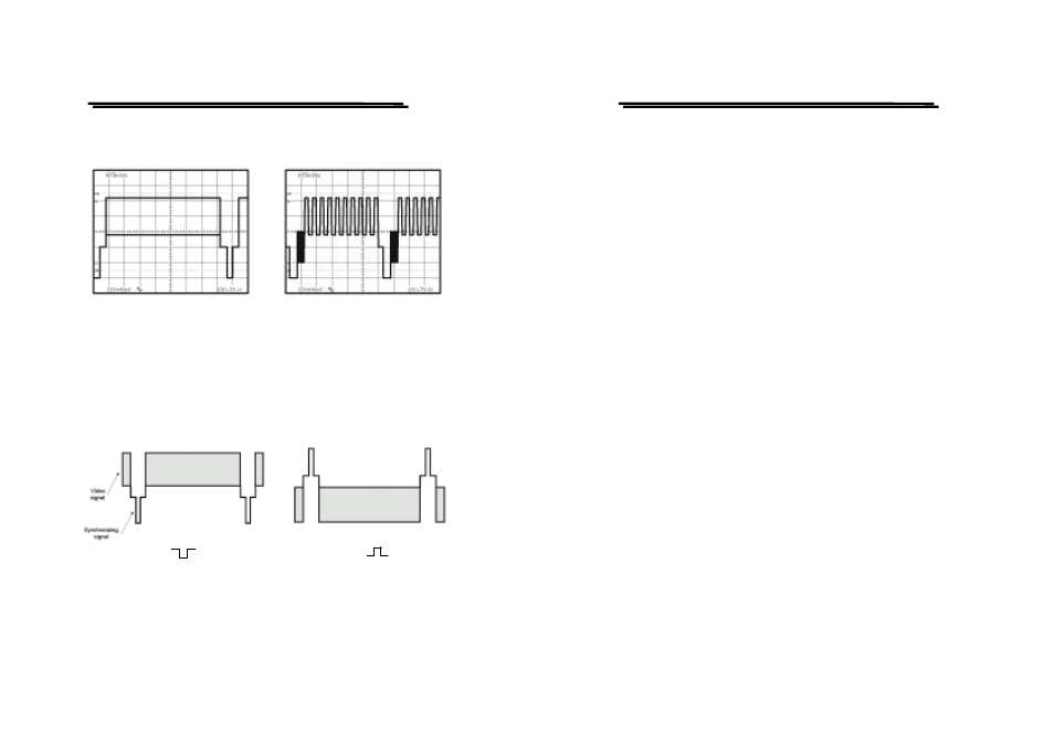
Figure 5-12(a) TV-V
Figure 5-12(b) TV-H
The polarity of the synchronization pulse is critical for the slope selection.
The figure 5-13(a) and 5-13(b) shows the examples of TV polarity
synchronization signals.
Figure 5-13(a) ( ) Sync signal. Figure 5-13(b) ( ) Sync signal
GOS-6103C OSCILLOSCOPE
USER MANUAL
48
5-6.Measurement Application
The oscilloscope has a cursor measurement system for making accurate,
direct-readout voltage, time, frequency and phase measurements. The
measurements described in this section are examples of typical
applications using this measurement system. After becoming familiar
with the controls, indicators, and capabilities of the instrument, you can
develop convenient methods to make the special measurement for your
own applications.
Proceed a measurement by using the cursor according to the following
steps:
1. Pressing and holding the CURSOR FUNCTION-ON/OFF pushbutton
to turn on the cursor and measurement readout.
2. Briefly pressing the pushbutton to select the seven measurement
function in the sequence as below:
△ V —△V% —△VdB —△T —△T% —1/△T —△Θ —△V
3. If the associated indicator CURSOR POS-LED is lighted, rotate the
C1-POSITION control to position the cursor 1 and rotate the
C2-POSITION control to position the cursor 2.
4. Read the measurement value on the screen. Typical measurement
readouts and applications are shown in Figure 5-14. The measurement
values are automatically controlled by the VOLTS/DIV and TIME/DIV
control settings.