GW Instek GOS-6103C User Manual
Page 13
GOS-6103C OSCILLOSCOPE
USER MANUAL
21
coefficient (reduce the deflection speed) and the deflection coefficient
becomes uncalibrated. Instead of “A=10μs”, the readout then displays
“A>10μs” indicating the uncalibrated condition. This setting is stored
if the instrument is switched to ALT or DELAY time base mode.
Switch off the VAR by pressing and holding the pushbutton of time
base mode again, then set the time deflection coefficient back into the
calibrated condition.
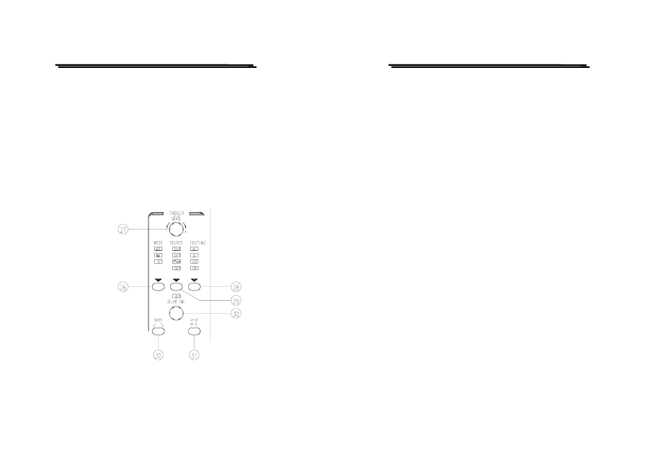
Trigger controls
The trigger controls determine the sweep start timing for both signal and
dual trace operation.
GOS-6103C OSCILLOSCOPE
USER MANUAL
22
(26)MODE – Pushbutton and indicator LEDs.
Pressing the pushbutton to select the trigger mode. The actual setting
is indicated by a LED.
Each time when the MODE pushbutton is pressed the trigger mode
changes in the sequence:
ATO—NML—TV—ATO
ATO (Auto)
Select the automatic mode, the sweep free-runs will display a baseline
trace when there is no trigger signal or the frequency is below 10Hz.
The setting of triggering level changed only when the TRIGGER
LEVEL control is adjusted to a new level setting.
NML (Normal)
Select the normal mode, the input signal will trigger the sweep when
the TRIGGER LEVEL control is set within the peak-to-peak limits of
an adequate trigger signal. When the sweep is not triggered, no
baseline trace will be displayed.
TV
Separate the video sync signal from the composite waveform and
direct it to the triggering circuit. The horizontal or vertical sync signals
are selected by TV-V/TV-H pushbutton. Please refer to the
TV-V/TV-H (31).
(27)LEVEL—Control knob
Turning the control knob causes a different trigger input setting
(voltage), and set to a suitable position for the starting of triggered
sweep of the waveform. An approximate trigger level setting (voltage)
value will be displayed in the readout. When rotate clockwise the
control knob, the trigger point moves toward the positive peak of the
trigger signal and rotate it counterclockwise to move the trigger point
toward the negative peak of the trigger signal.