GW Instek GOS-6103C User Manual
Page 17
GOS-6103C OSCILLOSCOPE
USER MANUAL
29
(34) MEMO- 9 —SAVE/RECALL
The instrument contains 10 non-volatile memories, which can be used
by the operator to save instrument setting and to recall them. It relates
to all controls which are electronically selected.
Press or pushbutton to select the memory location. The
readout then indicates the letter “MEN” followed by a cipher between
0 and 9. Each time the pushbutton is briefly pressed the memory
location cipher increases until the number 9 is reached. The
pushbutton is similar but decreases the memory location cipher until
the number 0 is reached. Pressing and holding SAVE for approx. 3
seconds to write the instrument settings in the memory and indicate
the associated readout information of “SAVED”.
To recall a front panel setup, select a memory location as described
above. Recall the settings by pressing and holding the RECALL
pushbutton for approx. 3 seconds, the readout then indicates the
associated readout information of “RECALLED”.
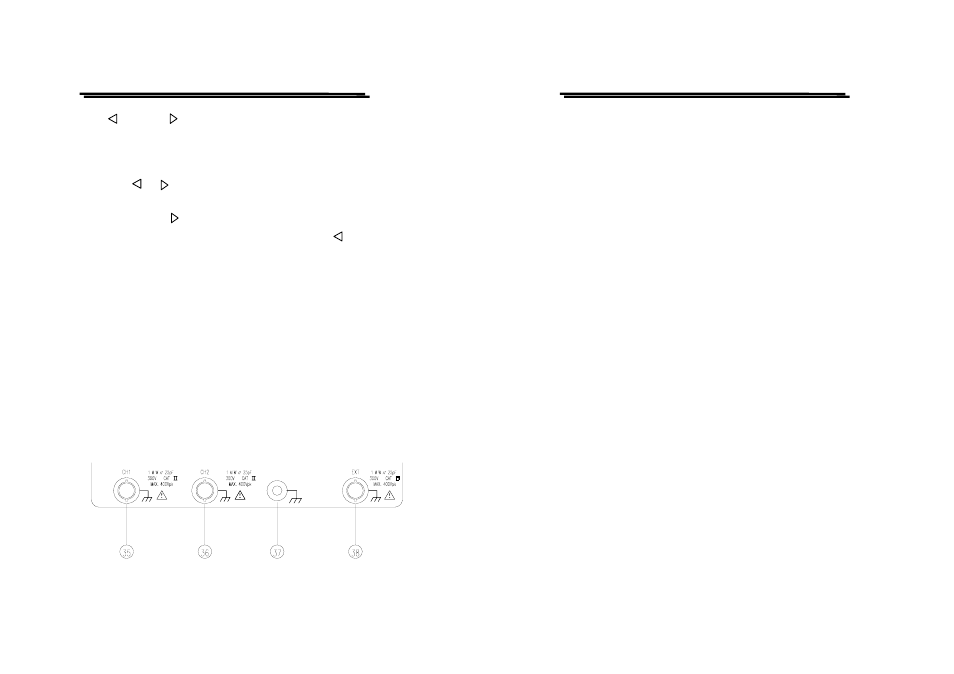
Input connectors
The input section is where the input signals are commonly connected to
the oscilloscope.
GOS-6103C OSCILLOSCOPE
USER MANUAL
30
(35)CH1—Input BNC socket
This BNC socket is the signal input for channel 1. In X-Y mode,
signals at this input are used for the Y or X deflection. The outer
(ground) connection is galvanically connected to the instrument
ground and consequently to the safety earth contact of the line/mains
plug.
(36)CH2—Input BNC socket
This BNC socket is the signal input for channel 2. In X-Y mode,
signals at this input are used for the X or Y deflection. The outer
(ground) connection is galvanically connected to the instrument
ground and consequently to the safety earth contact of the line/mains
plug.
(37)Ground socket—Banana Socket galvanically connected to safety
earth.
This socket can be used a reference potential connection for DC and
low frequency signal measurement purposes.
(38)EXT—This BNC socket is the external trigger signal input.
In dual X-Y mode, signals at this input are used for the X deflection.
Pressing the TRIG. SOURCE (29) pushbutton until the information of
“EXT, slope, coupling” is shown up in the readout and the TRIG.
SOURCE “EXT” LED is lighted, switches the input on.
The outer (ground) connection is galvanically connected to the
instrument ground and consequently to the safety earth contact of the
line/mains plug.
The maximum input voltages of the instrument input terminals and probe
input terminals are listed in the section of 3-6. “Withstanding voltage of
Input terminals”. Do not apply voltage higher than the limit.