GW Instek GOS-652G User Manual
Page 27
⎯ 22 ⎯
(3) Function of SLOPE switch:
This switch selects the slope (polarity) of the triggering signal
as shown in Figure 4-9.
“
+” : When set in the “+” state, triggering occurs as the triggering
signal crosses the triggering lever in the positive-going direction.
“-“ : When set in the “-” state, triggering occurs as the triggering
signal crosses the triggering lever in the negative-going direction.
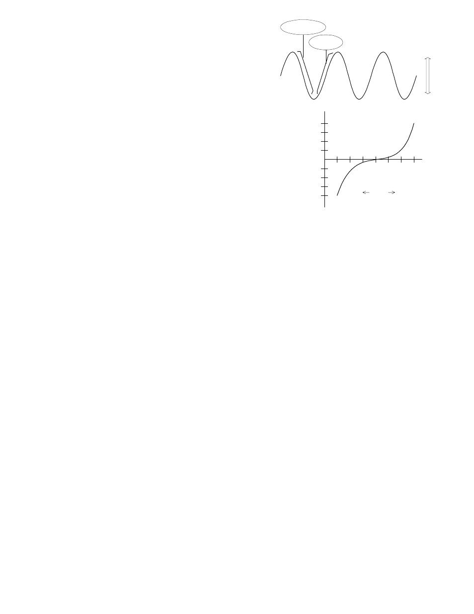
(4) Function of Level (LOCK) control:
The function of this control is to adjust the triggering level
and display a stationary image. At the instant, the triggering
signal has crossed the triggering level set by the control, the
sweep is triggered and a waveform is displayed on the screen.
The trigger level changes in the positive direction(upward) as
this control knob is turned clockwise, and it changes in the
negative direction(downward) as the knob is turned counter
clockwise. The characteristic changes are as shown
in Figure 4-10.
LEVEL LOCK:
When LEVEL LOCK push switch is engaged, the triggering
level is automatically maintained within the amplitude of
the triggering signal, and stable triggering is made without requiring
622G / 623G/626G :
level adjustment (although jitter may not be suppressed when in the ALT mode).
50 Hz-
5MHz
: 1.0DIV (0.15V) or less
This automatic level lock function is effective when the signal amplitude on the
5MHz-
20MHz
: 2.0DIV (0.25V) or less
screen or the input voltage of the external triggering signal is within the
635G: 50 Hz-
5MHz
: 1.0DIV (0.15V) or less
following range:
5MHz- 35MHz
: 2.0DIV (0.25V) or less
652G / 653G / 658G :
50
Hz- 10MHz
: 1.0DIV (0.15V) or less
10 MHz-
40MHz
: 2.0DIV (0.25V) or less
+
-
Level
Slope "-" Range
Slope "+"
Range
Figure 4-9
Figure 4-10
Trigger level
120
O
60
O
30
O
0
120
O
60
O
30
O
4
3
2
1
4
3
2
1
Center
Right
Left
Level knob rotation angle
DIV
Graticule scale
equivalent (DIV)