5 add operation, 6 x-y operation and ext hor operation, X-y operation – GW Instek GOS-652G User Manual
Page 24
⎯ 19 ⎯
4.5 ADD Operation
An algebraic sum of the CH 1 and CH 2 signals can be displayed on the screen by setting the VERT MODE switch to the ADD
state. The displayed signal is the difference between CH 1 and CH 2 signals if the CH 2 INV push switch is engaged.
For accurate addition or subtraction, it is a prerequisite that the sensitivities of the two channels are adjusted accurately at the same
value by means of the VARIABLE knobs. Vertical positioning can be made with the
∆∇ POSITION knob of either channel. In view of
the linearity of the vertical amplifiers, it is most advantage to set both knobs in their mid-positions.
4.6 X-Y Operation and EXT HOR Operation
When the TIME/DIV switch is set in the X-Y/EXT HOR state, the internal sweep circuit is disconnected and the trace in the
horizontal direction is driven by the signal selected by the SOURCE switch. When the SOURCE switch is set to the CH 1 X-Y position,
the oscilloscope operates as an X-Y scope with the CH 1 signal for the X-axis; when it is set to the EXT position, the oscilloscope
operates in the EXT HOR(external sweep) mode.
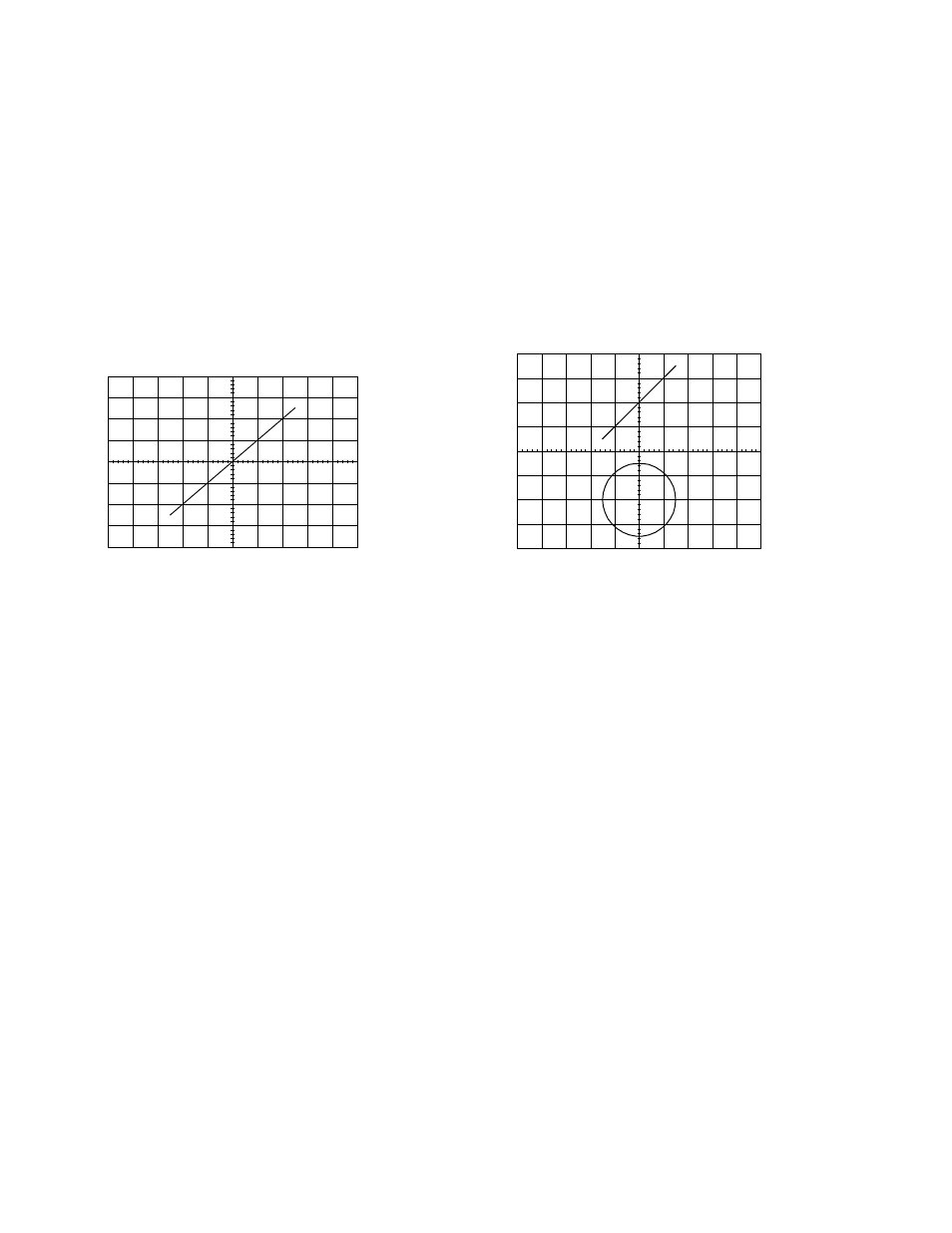
X-Y Operation
The X-Y operation is with CH 1 as X-axis and CH 2 as Y-axis. The bandwidth of the X-axis becomes DC to 1MHz(-3dB)(or DC to
2MHz for 652G, 653G, 658G) and the horizontal POSITION control is directly used as the X-axis POSITION control. For the Y-axis, the
CH 2(X-Y) should be selected by the VERT MODE switch.
Figure 4-6
Y axis (CH2)
X axis
(CH1)
Figure 4-7
Dual-Channel
X-Y Operation
Note: When high frequency signals are displayed in the X-Y operation, pay attention to the frequency bandwidths and phase difference
between X and Y-axis.