Alarm/trouble annunciation of zones – Fire-Lite LDM-32F Lamp Drivers User Manual
Page 54
Appendix C: MS-9600
Configuration
54
LDM-32F PN 50055:C 03/20/01
Alarm/Trouble Annunciation of Zones
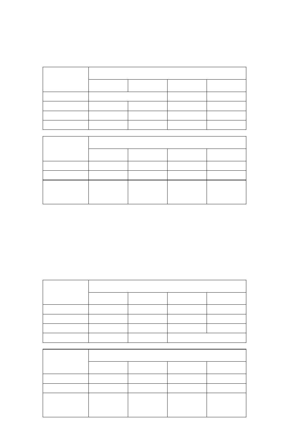
The table below (also see Figure 36 on page 55) illustrates the configuration
of the LDM Series modules to annunciate the alarm and trouble states for all
99 software zones, and two NACs, with the first eight points of address ‘01’
dedicated to the MS-9600 system functions (see Figure 37 on page 55).
Table 26 Alarm/Trouble Setup
Alarm/Trouble Annunciation of Zones - 8-Point Shift
The table below (also see Figure 36 on page 55) illustrates the configuration
of the LDM Series modules to annunciate the alarm and trouble states for all
99 software zones, and one NAC, with the last eight points of address ‘01’
dedicated to the MS-9600 system functions as listed below (see Figure 38 on
page 55).
Table 27 Alarm/Trouble Setup with Shift
LDM Module
Address ‘01’
LDM Output Connectors
J5
J6
J7
J8
LDM-32F
System Functions
Z1 to Z4
Z5 to Z8
1st LDM-E32F
Z9 to Z12
Z13 to Z16
Z17 to Z20
Z21 to Z24
2nd LDM-E32F
Z25 to Z28
Z29 to Z32
Z33 to Z36
Z37 to Z40
3rd LDM-E32F
Z41 to Z44
Z45 to Z48
Z49 to Z52
Z53 to Z56
LDM Module
Address ‘02’
LDM Output Connectors
J5
J6
J7
J8
LDM-32F
Z57 to Z60
Z61 to Z64
Z65 to Z68
Z69 to Z72
1st LDM-E32F
Z73 to Z76
Z77 to Z80
Z81 to Z84
Z85 to Z88
2nd LDM-E32F
Z89 to Z92
Z93 to Z96
Z97 to Z99 &
NAC1, NAC2
ON
LDM Module
Address ‘01’
LDM Output Connectors
J5
J6
J7
J8
LDM-32F
Z1 to Z4
Z5 to Z8
Z9 to Z12
Z13 to Z16
1st LDM-E32F
Z17 to Z20
Z21 to Z24
Z25 to Z28
Z29 to Z32
2nd LDM-E32F
Z33 to Z36
Z37 to Z40
Z41 to Z44
Z45 to Z48
3rd LDM-E32F
Z49 to Z52
Z53 to Z56
System Functions
LDM Module
Address ‘02’
LDM Output Connectors
J5
J6
J7
J8
LDM-32F
Z57 to Z60
Z61 to Z64
Z65 to Z68
Z69 to Z72
1st LDM-E32F
Z73 to Z76
Z77 to Z80
Z81 to Z84
Z85 to Z88
2nd LDM-E32F
Z89 to Z92
Z93 to Z96
Z97 to Z99 &
NAC1, NAC2
ON