Figure 30 connections for alarm/trouble, J5 j6, J7 j8 – Fire-Lite LDM-32F Lamp Drivers User Manual
Page 44
Appendix B: MS-9200
Configuration
44
LDM-32F PN 50055:C 03/20/01
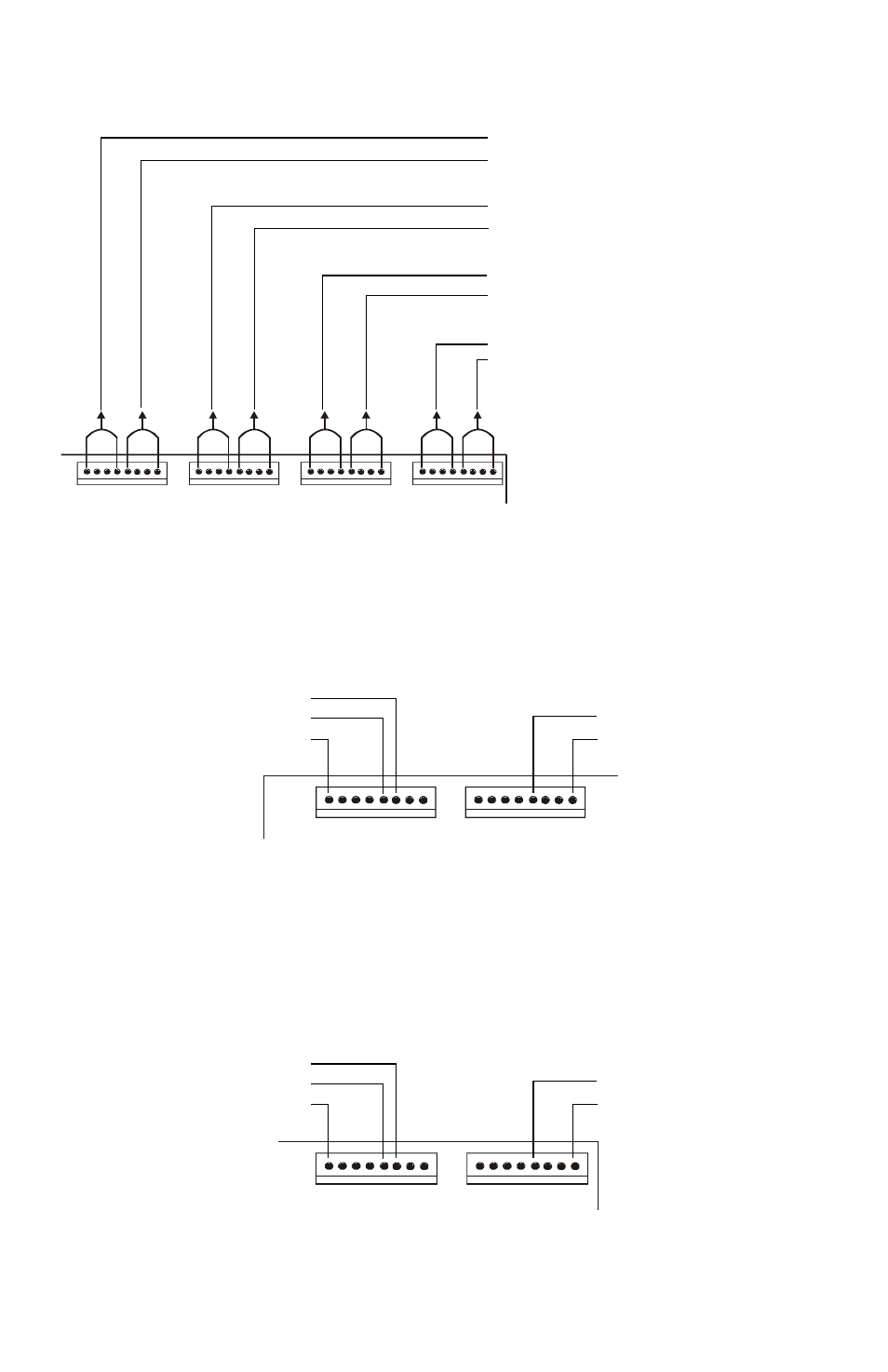
The figure below is an example of the connections used when setting the LDM
module for Alarm/Trouble mode.
Figure 30 Connections for Alarm/Trouble
The figure below illustrates pin usage of output connectors for system functions
in alarm/trouble mode.
Figure 31 System Functions to Output Connectors - 1
The figure below illustrates pin usage of output connectors for system functions
in alarm/trouble mode with 8-Point shift selected.
Figure 32 System Functions to Output Connectors - 2
1
2
3
4
5
6
7
8
9
10
11
12
13
14
15
16
17
18
19
20
21
22
23
24
25
26
27
28
29
30
31
32
J5
J6
J7
J8
LC
M32
F
-c
onn.cd
r
Alarm - First 4 Zones or Points
Trouble - First 4 Zones or Points
Alarm - Second 4 Zones or Points
Trouble - Second 4 Zones or Points
Alarm - Third 4 Zones or Points
Trouble - Third 4 Zones or Points
Alarm - Fourth 4 Zones or Points
Trouble - Fourth 4 Zones or Points
1
2
3
4
5
6
7
8
9
10
11
12
13
14
15
16
J5
J6
Supervisory (Yellow)
AC Fail (Red)
Signals Silenced (Yellow)
System Trouble (Yellow)
System Alarm (Red)
System Status Indicators
Note: Pins not marked are not used
LC
M
32F-
J
5J6.cd
r
17
18
18
20
21
22
23
24
25
26
27
28
29
30
31
32
J7
J8
Supervisory (Yellow)
AC Fail (Red)
Signals Silenced (Yellow)
System Trouble (Yellow)
System Alarm (Red)
System Status Indicators
LC
M3
2F-
J
7J8.cdr
Note: Pins not marked are not used