Wiring for lamp/led, Wiring for lamp/led 2. installation, Point status leds resistor system trouble led – Fire-Lite LDM-32F Lamp Drivers User Manual
Page 23
Wiring for Lamp/LED
2. Installation
LDM-32F PN 50055:C 03/20/01
23
Wiring for Lamp/LED
• All LEDs must be located in the same room as the LDM modules.
• For 5 volt output use a 680 ohm, 1/4-watt resistors for each point if
using 2 mA LEDs.
• For 24 volt output use a 10K ohm, 1/4-watt resistors for each point if
using 2 mA LEDs.
• LEDs: use red for alarm points, yellow for trouble points and green
for output points.
• Use the cables supplied in the cable kit to wire connectors on LDM.
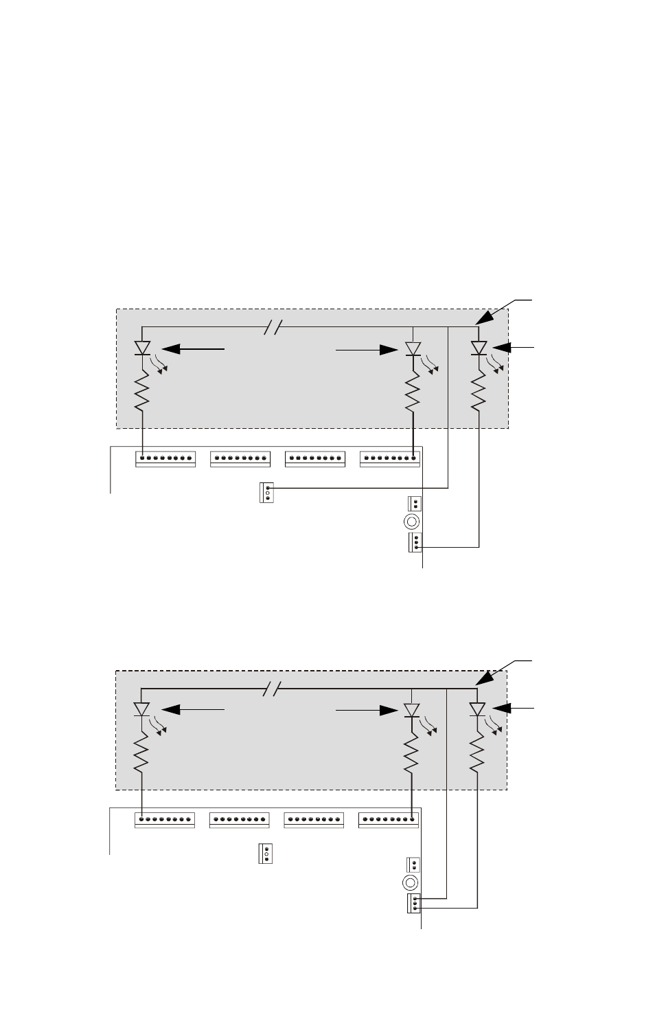
The figure below illustrates LEDs being powered by the 5 volt output from
LDM-32F, J11 pin 1.
Figure 14 Typical LDM-to-Graphics Display Connection @ 5VDC
The figure below illustrates LEDs being powered by the 24 volt output from
LDM-32F, J9 pin 3.
Figure 15 Typical LDM-to-Graphics Display Connection @ 24VDC
J10
J9
LAMP
POWER
J11
1
2
3
4
5
6
7
8
9
10
11
12
13
14
15
16
17
18
19
20
21
22
23
24
25
26
27
28
29
30
31
32
J5
J6
J7
J8
Point Status LEDs
Resistor
System
Trouble
LED
LD
M32
F
-5
vol
tout.
c
dr
Custom Graphic Display
Wiring is not
supervised
LDM-32F
J10
J9
LAMP
POWER
J11
1
2
3
4
5
6
7
8
9
10
11
12
13
14
15
16
17
18
19
20
21
22
23
24
25
26
27
28
29
30
31
32
J5
J6
J7
J8
LD
M3
2F-
24vol
to
ut.cdr
Custom Graphic Display
Point Status LEDs
Resistor
Wiring is not
supervised
System
Trouble
LED
LDM-32F