Key-lock control switch security, Related documentation – Fire-Lite LDM-32F Lamp Drivers User Manual
Page 15
Related Documentation
1. Introduction
LDM-32F PN 50055:C 03/20/01
15
Each LDM-CBL48 cable kit includes:
• (4) P/N 75147, 48" cable consisting of 8 stranded, multicolored
conductors. Cables connect to J5, J6, J7 and J8.
• (1) P/N 75150, 48" cable consisting of 10 stranded, multicolored
conductors. Connects to J1, optional control switches.
• (1) P/N 75148, 48" cable consisting of 2 stranded, single color
conductors. Connects to J1, Lamp Test Switch
.
• (1) P/N 75149, 48" cable consisting of 3 stranded, multicolored
conductors. Connects to J9 or J11, Lamp Power.
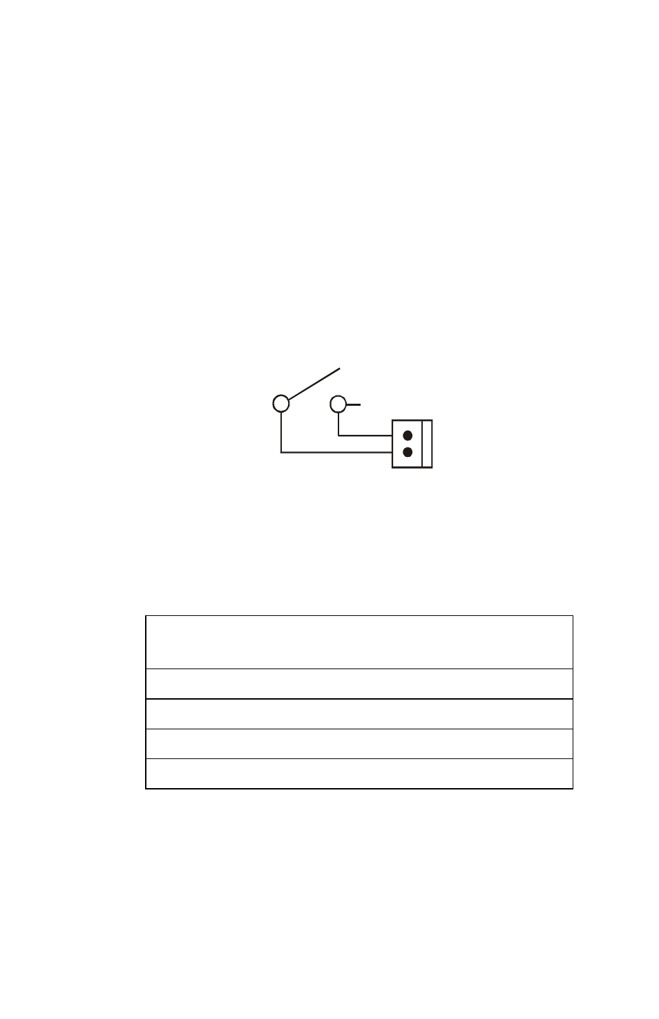
Key-lock Control Switch Security
A UL listed key-lock switch wired to J4 on the LDM-32F should be used to
provide access security for all control switches wired to that set of LDM
modules.
Note: Control switches will not function when the key-lock switch is in its closed position.
Figure 3 Key-lock Switch Wiring Diagram
Related Documentation
Further details about products referenced in this document can be found in the
manuals for the particular fire alarm control panel and components.
J4
2
1
Key Switch
LDM-32F
LD
M3
2F-
k
eysw
.cdr
Product
Part
Number
MS-9200 Fire Alarm Control Panel Instruction Manual
51003
MS-9600 Fire Alarm Control Panel Instruction Manual
51335
Sensiscan 2000 Fire Alarm Control Panel Instruction Manual
15017
CAB-3F Series Cabinets Installation Document
15391