Page 4 – Edwards Signaling 5536MHV-24 User Manual
Page 4
P/N 3100009 ISSUE 2
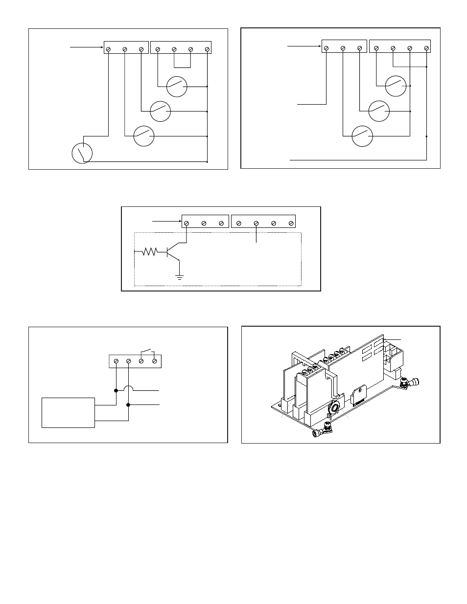
INPUT BOARD
PROCESSOR BOARD
MAIN BOARD
POTENTIOMETER FOR
VOLUME ADJUSTMENT
IN4
N
+VS
GND
PROGRAMMING
SWITCHES
(ON OTHER SIDE)
IN1
IN2
IN3
AUDIO INPUT BOARD
SW
1
SW
2
SW
3
SW
4
SYSTEM
CONSOLE
AUDIO (+)
RELAY
POWER SUPERVISION
(WHERE APPLICABLE)
AUDIO
+
AUDIO
-
AUDIO COUPLER BOARD
TO OTHER UNITS'
AUDIO COUPLER BOARDS
AUDIO (-)
NOTE:
Audio Signal
not to exceed 10Vrms
IN1
IN2
IN3
IN4
N
+VS
GND
(5V DC to 24V DC +/- 1%)
FROM CUSTOMER
CIRCUIT
CUSTOMER CIRCUIT
ON INPUT
BOARD
IN1
IN2
IN3
IN4
N
+VS
GND
K3
K2
K1
24V DC
Priority Signal
To Command
Line
K1 - K3
Local Priorities
On Input Board
IN1
IN2
IN3
IN4
N
+VS
GND
K3
K2
K1
On Input Board
Priority
Signal
Activation
Figure 9. PC Board Locations
Figure 8. Connecting Audio Signal, not to exceed
10Vrms, from Tone Generator to
5536M Audio Input Board
Figure 6. Connecting 24V DC Priority Signal to the
Input Board for Activation of External Audio Signal
Connected to Audio Input Board (Figure 8)
Figure 5. Installing with Multiple Dry Relay Contacts
Internally Generated Tones Only
Page 4
Figure 7. Installing with an open collector transistor for
24V DC tone initiation to IN1, IN2, IN3 or IN4